Detailed Description
The following description is presented to enable any person skilled in the art to make and use the disclosure, and is provided in the context of a particular application and its requirements. It will be apparent to those skilled in the art that various modifications to the disclosed embodiments are possible, and that the general principles defined in this application may be applied to other embodiments and applications without departing from the spirit and scope of the application. Thus, the present application is not limited to the described embodiments, but should be accorded the widest scope consistent with the claims.
It will be understood that the terms "system," "engine," "unit," "module," and/or "block" as used herein are methods for distinguishing different components, elements, components, parts, or assemblies of different levels in ascending order. However, these terms may be replaced by other expressions if the same purpose can be achieved.
Generally, the words "module," "unit," or "block" as used herein refers to logic embodied in hardware or firmware, or a collection of software instructions. The modules, units, or blocks described herein may be implemented as software and/or hardware and may be stored in any type of non-transitory computer-readable medium or another storage device. In some embodiments, software modules/units/blocks may be compiled and linked into an executable program. It should be understood that software modules may be invoked from other modules/units/blocks or from themselves, and/or may be invoked in response to detected events or interrupts. Software modules/units/blocks configured to execute on a computing device (e.g., processor 210 shown in fig. 2) may be provided on a computer readable medium, such as a compact disc, digital video disc, flash drive, magnetic disk, or any other tangible medium, or as a digital download (and may be initially stored in a compressed or installable format, requiring installation, decompression, or decryption prior to execution). The software code herein may be stored in part or in whole in a memory device of a computing device performing the operations and employed in the operations of the computing device. The software instructions may be embedded in firmware (e.g., erasable programmable read-only memory (EPROM)). It should also be understood that hardware modules/units/blocks may be included in connected logic components, such as gates and flip-flops, and/or may include programmable units, such as programmable gate arrays or processors. The modules/units/blocks or computing device functions described herein may be implemented as software modules/units/blocks, but may be represented in hardware or firmware. Generally, the modules/units/blocks described herein refer to logical modules/units/blocks, which may be combined with other modules/units/blocks or divided into sub-modules/sub-units/sub-blocks, even though they are physical organizations or memory devices. The description may apply to the system, the engine, or a portion thereof.
The terminology used in the description presented herein is for the purpose of describing particular example embodiments only and is not intended to be limiting. As used herein, the singular forms "a", "an" and "the" are intended to include the plural forms as well, unless the context clearly indicates otherwise. It will be further understood that the terms "comprises" and/or "comprising," when used in this specification, specify the presence of stated features, integers, steps, operations, components, and/or components, but do not preclude the presence or addition of one or more other features, integers, steps, operations, components, and/or groups thereof.
These and other features, aspects, and advantages of the present application, as well as the methods of operation and functions of the related elements of structure and the combination of parts and economies of manufacture, will become more apparent upon consideration of the following description of the accompanying drawings, all of which form a part of this specification. It is to be understood, however, that the drawings are designed solely for the purposes of illustration and description and are not intended as a definition of the limits of the application. It should be understood that the drawings are not to scale.
The flow diagrams used in this application are examples of operations that may be implemented in addition to systems according to some embodiments of the application. It should be understood that the operations in the flow diagrams may be performed out of order. Rather, various steps may be processed in reverse order or simultaneously. Also, one or more other operations may be added to the flowcharts. One or more operations may also be deleted from the flowchart.
The application relates to a method and a system for magnetic resonance diffusion image reconstruction. The system may acquire at least two sets of imaging data. Each of the at least two sets of imaging data may be generated by magnetic resonance signals acquired by a magnetic resonance scanner by scanning the subject using a diffusion sequence. The system may also determine one or more correction coefficients related to errors caused by the diffusion sequence for each of the at least two sets of imaging data. The correction coefficients may be used to correct phase errors and/or amplitude errors caused by the diffusion sequence. The system may also determine the corrected at least two sets of imaging data based on one or more correction coefficients corresponding to each of the at least two sets of imaging data. Each of the at least two sets of imaging data may be corrected by one or more correction coefficients (e.g., amplitude correction coefficients). Correcting the imaging data may reduce or remove anomalous signals (e.g., noise) caused by the amplitude error, thereby improving the signal-to-noise ratio (SNR) of the imaging data. Alternatively or additionally, at least two sets of imaging data (e.g., the corrected at least two sets of imaging data) may be averaged in the complex domain (i.e., complex domain averaging), which may reduce the accumulated noise, thereby improving the SNR of the imaging data. The system may generate a target magnetic resonance image based on the processed (e.g., corrected and/or averaged) imaging data.
Figure 1 is a schematic diagram of an exemplary magnetic resonance system 100 shown in accordance with some embodiments of the present application. As shown, the magnetic resonance system 100 may include a magnetic resonance scanner 110, a processing device 120, a storage device 130, one or more terminals 140, and a network 150. The components in the magnetic resonance system 100 may be connected in one or more of a variety of ways. By way of example only, as shown in figure 1, the magnetic resonance scanner 110 may be connected to the processing device 120 through a network 150. As another example, the magnetic resonance scanner 110 may be directly connected to the processing device 120, e.g., the magnetic resonance scanner 110 and the processing device 120 may be connected as indicated by the double-headed arrow in dashed lines. As yet another example, storage device 130 may be connected directly to processing device 120 (not shown in FIG. 1) or through network 150. As yet another example, one or more terminals 140 may be connected directly with processing device 120 (as indicated by the double-headed arrow in the dashed line connecting terminal 140 and processing device 120) or through network 150.
The magnetic resonance scanner 110 may scan a subject or a portion thereof located within its examination region and generate magnetic resonance signals related to the subject or portion thereof. In this application, the terms "object" and "object" are used interchangeably. In some embodiments, the subject may include a body, a substance, or the like, or a combination thereof. In some embodiments, the subject may include a particular part of the body, such as the head, chest, abdomen, etc., or a combination thereof. In some embodiments, the subject may include a specific organ, such as the heart, esophagus, trachea, bronchi, stomach, gall bladder, small intestine, colon, bladder, ureter, uterus, fallopian tube, and the like. The magnetic resonance scanner 110 may include a magnet assembly, a gradient coil assembly, and a Radio Frequency (RF) coil assembly.
The magnet assembly may generate a first magnetic field (also referred to as main magnetic field) for polarizing the object to be scanned. The magnet assembly may include permanent magnets, superconducting electromagnets, resistive electromagnets, and the like.
The gradient coil assembly may generate a second magnetic field (also referred to as a gradient magnetic field). The gradient coil assembly may include an X-gradient coil, a Y-gradient coil, and a Z-gradient coil. The gradient coil assembly may generate one or more magnetic field gradient pulses in the X-direction (Gx), Y-direction (Gy), and Z-direction (Gz) with respect to the main magnetic field to encode spatial information of the subject. In some embodiments, the X direction may be designated as the frequency encoding direction, while the Y direction may be designated as the phase encoding direction. In some embodiments, Gx may be used for frequency encoding or signal readout, which is commonly referred to as a frequency encoding gradient or readout gradient. In some embodiments, Gy may be used for phase encoding, commonly referred to as phase encoding gradients. In some embodiments, Gz may be used for slice selection to acquire two-dimensional k-space data. In some embodiments, Gz may be used for phase encoding to acquire k-space data in three dimensions.
The RF coil assembly may include at least two RF coils. The RF coils may include one or more RF transmit coils and/or one or more RF receive coils. The RF transmit coil may transmit RF pulses to the object to be scanned. Under the synergistic effect of the main magnetic field \ gradient magnetic field and the RF pulse, magnetic resonance signals related to the subject can be generated from the pulse sequence. The RF receive coil may acquire magnetic resonance signals from the subject according to a pulse sequence. The magnetic resonance signals may also be referred to as echo signals. The magnetic resonance signals may be processed using a transformation operation (e.g., fourier transform) to fill k-space to acquire k-space data. The pulse sequence may be defined by the imaging parameters and the arrangement of the imaging parameters in time sequence. For example, the pulse sequence may be defined by one or more parameters related to time (e.g., repetition Time (TR), acquisition Time (TA), echo Time (TE), etc.). Exemplary pulse sequences may include spin echo sequences, gradient echo sequences, diffusion sequences, inversion recovery sequences, and the like, or combinations thereof. For example, the spin echo sequence may include Fast Spin Echo (FSE), vortex spin echo (TSE), relaxation enhanced fast acquisition (RARE), half fourier acquisition single shot spin echo (HASTE), vortex gradient spin echo (TGSE), and the like, or combinations thereof. The gradient echo sequence may comprise an Echo Planar Imaging (EPI) sequence. In some embodiments, the pulse sequence may comprise a diffusion sequence. The diffusion sequence may include at least one diffusion block associated with one or more parameters of a diffusion gradient and at least one imaging block associated with one or more scan parameters (e.g., parameters associated with one or more encoding gradients applied in a scan). In some embodiments, the pulse sequence may include a single-shot pulse sequence (e.g., single-shot FSE, single-shot EPI, etc.), a multiple-shot pulse sequence (e.g., multiple-shot FSE, multiple-shot EPI, etc.), in some embodiments, for a single-shot pulse sequence (e.g., single-shot FSE, single-shot EPI, etc.), an RF pulse may be applied once within the TR, and one or more echo signals may be sampled within the TR. For multiple excitation pulse sequences (e.g., multiple excitation FSE, multiple excitation EPI, etc.), RF pulses may be applied multiple times within the TR, and one or more echo signals may be sampled during each excitation or excitation.
In some embodiments, the magnetic resonance scanner 110 may include an analog-to-digital converter (ADC) (not shown in figure 1). The analog-to-digital converter may convert magnetic resonance signals received by the one or more RF receive coils into magnetic resonance imaging data. The analog-to-digital converter may be a direct conversion ADC, a successive approximation ADC, a ramp comparison ADC, a wilkinson ADC, an integral ADC, an incremental encoding ADC, a pipelined ADC, a sigma-incremental ADC, or the like, or a combination thereof.
The processing device 120 can process data and/or information acquired and/or extracted from the magnetic resonance scanner 110, the terminal 140, the storage device 130, and/or other storage devices. For example, the processing device 120 may acquire at least two sets of imaging data and reconstruct a target magnetic resonance image based on the at least two sets of imaging data. For another example, the processing device 120 may determine one or more correction coefficients related to errors caused by the diffusion sequence for each of the at least two sets of imaging data, and determine the corrected at least two sets of imaging data based on the one or more correction coefficients corresponding to each of the at least two sets of imaging data. Then, the processing device 120 may determine average imaging data by averaging the corrected at least two sets of imaging data in the complex domain, and generate a target magnetic resonance image based on the average imaging data. In some embodiments, the reconstructed image may be transmitted to the terminal 140 and displayed on one or more display devices in the terminal 140. In some embodiments, the processing device 120 may be a single server or a group of servers. The server groups may be centralized or distributed. In some embodiments, the processing device 120 may be local or remote. For example, the processing device 120 may access information and/or data stored in the magnetic resonance scanner 110, the terminal 140, and/or the storage device 130 via the network 150. As another example, the processing device 120 may be directly connected with the magnetic resonance scanner 110, one or more terminals 140, and/or the storage device 130 to access stored information and/or data. In some embodiments, the processing device 120 may be implemented on a cloud platform. By way of example only, the cloud platform may include a private cloud, a public cloud, a hybrid cloud, a community cloud, a distributed cloud, an internal cloud, a multi-tiered cloud, and the like, or any combination thereof. In some embodiments, the processing device 120 may be implemented on a computing device 200 having one or more components shown in FIG. 2 in the present application.
Storage device 130 may store data and/or instructions. In some embodiments, storage device 130 may store data obtained from terminal 140 and/or processing device 120. For example, the storage device 130 may store at least two sets of imaging data (e.g., k-space data, magnetic resonance images), intermediate data generated in magnetic resonance image reconstruction (e.g., one or more correction coefficients, corrected imaging data, average imaging data), a target magnetic resonance image, and so forth. In some embodiments, storage device 130 may store data and/or instructions that processing device 120 may perform or use to perform the example methods described herein. In some embodiments, storage device 130 may include a mass storage device, a removable storage device, volatile read-write memory, read-only memory (ROM), the like, or any combination thereof. Exemplary mass storage devices may include magnetic disks, optical disks, solid state drives, and the like. Exemplary removable memories may include flash drives, floppy disks, optical disks, memory cards, compact disks, magnetic tape, and the like. Exemplary volatile read and write memory can include Random Access Memory (RAM). Exemplary RAM may include Dynamic Random Access Memory (DRAM), Double Data Rate Synchronous Dynamic Random Access Memory (DDRSDRAM), Static Random Access Memory (SRAM), thyristor random access memory (T-RAM), zero capacitance random access memory (Z-RAM), and the like. Exemplary ROMs may include mask ROM (mrom), programmable ROM (prom), erasable programmable ROM (pemom), electrically erasable programmable ROM (eeprom), compact disk ROM (CD-ROM), and digital versatile disk ROM, among others-in some embodiments, storage device 130 may be implemented on a cloud platform. By way of example only, the cloud platform may include a private cloud, a public cloud, a hybrid cloud, a community cloud, a distributed cloud, an internal cloud, a multi-tiered cloud, and the like, or any combination thereof.
In some embodiments, the storage device 130 may be connected with a network 150 to communicate with one or more components of the magnetic resonance system 100 (e.g., the processing device 120, one or more terminals 140, etc.). One or more components of the magnetic resonance system 100 may access data or instructions stored in the storage device 130 through the network 150. In some embodiments, the storage device 130 may be directly connected to or in communication with one or more components of the magnetic resonance system 100 (e.g., the processing device 120, one or more terminals 140, etc.). In some embodiments, the storage device 130 may be part of the processing device 120.
The terminal 140 may include a mobile device 140-1, a tablet computer 140-2, a laptop computer 140-3, etc., or any combination thereof. In some embodiments, mobile device 140-1 may include a smart home device, a wearable device, a smart mobile device, a virtual reality device, an augmented reality device, and the like, or any combination thereof. In some embodiments, the smart home devices may include smart lighting devices, smart appliance control devices, smart monitoring devices, smart televisions, smart cameras, interphones, and the like, or any combination thereof. In some embodiments, the wearable device may include a smart bracelet, a smart lace, smart glasses, a smart helmet, a smart watch, a smart garment, a smart backpack, a smart accessory, or the like, or any combination thereof. In some embodiments, the smart mobile device may include a smart phone, a Personal Digital Assistant (PDA), a gaming device, a navigation device, a point of sale (POS), etc., or any combination thereof. In some embodiments, the virtual reality device and/or the augmented reality device may include a virtual reality helmet, virtual reality glasses, virtual reality eyeshields, augmented reality helmets, augmented reality glasses, augmented reality eyeshields, and the like, or any combination thereof. For example, the virtual reality device and/or augmented reality device may include google glasses, Oculus Rift, Hololens, Gear VR, and the like. In some embodiments, one or more terminals 140 may remotely operate the magnetic resonance scanner 110. In some embodiments, the terminal 140 may operate the magnetic resonance scanner 110 via a wireless connection. In some embodiments, one or more terminals 140 may receive information and/or instructions input by a user and transmit the received information and/or instructions to the magnetic resonance scanner 110 or the processing device 120 via the network 150. In some embodiments, one or more terminals 140 may receive data and/or information from processing device 120. In some embodiments, one or more terminals 140 may be part of processing device 120. In some embodiments, the terminal 140 may be omitted.
In some embodiments, the one or more terminals 140 may transmit and/or receive information for magnetic resonance image reconstruction to the processing device 120 via a user interface. The user interface may be implemented on the terminal 140 in the form of an application for magnetic resonance image reconstruction. The user interface implemented on one or more terminals 140 may be configured to facilitate communication between a user and the processing device 120. In some embodiments, the user may input a magnetic resonance image reconstruction request via a user interface implemented on the terminal 140. The terminal 140 may send a magnetic resonance image reconstruction request to the processing device 120 for reconstructing a magnetic resonance image as described elsewhere in this application (e.g., figure 5 and related description). In some embodiments, a user may input and/or adjust scan or imaging parameters of a pulse sequence via a user interface. In some embodiments, the user interface may facilitate presentation or display of information and/or data (e.g., signals) received from the processing device 120 related to magnetic resonance image reconstruction. For example, the information and/or data may include results generated by the processing device 120 in image reconstruction. For example, the results may include one or more images (e.g., 2D images, 3D images, etc.), one or more data graphs, one or more words, one or more numbers, one or more models for magnetic resonance image reconstruction, parameters used in such image reconstruction, and so forth. In some embodiments, the information and/or data may be further configured to cause the terminal 140 to display the results to the user.
The network 150 may include any suitable network that may facilitate the exchange of information and/or data for the magnetic resonance system 100. In thatIn some embodiments, one or more components of the magnetic resonance system 100 (e.g., the magnetic resonance scanner 110, one or more terminals 140, the processing device 120, or the storage device 130) may communicate information and/or data with one or more other components of the magnetic resonance system 100. For example, the processing device 120 may acquire magnetic resonance signals from the magnetic resonance scanner 110 via the network 150. As another example, processing device 120 may obtain user instructions from terminal 140 via network 150. In some embodiments, the network 150 may be any type of wired or wireless network or combination thereof. The network 150 may be and/or include a public network (e.g., the internet), a private network (e.g., a Local Area Network (LAN), a Wide Area Network (WAN), etc.), a wired network (e.g., ethernet), a wireless network (e.g., an 802.11 network, a Wi-Fi network, etc.), a cellular network (e.g., a Long Term Evolution (LTE) network), a frame relay network, a virtual private network ("VPN"), a satellite network, a telephone network, a router, a hub, a switch, a server computer, and/or any combination thereof. By way of example only, network 150 may include a cable network, a wireline network, a fiber optic network, a telecommunications network, an intranet, a Wireless Local Area Network (WLAN), a Metropolitan Area Network (MAN), a Public Switched Telephone Network (PSTN), Bluetooth, or a network such as a Bluetooth networkTMNetwork and ZigBeeTMA network, a Near Field Communication (NFC) network, etc., or any combination thereof. In some embodiments, the network 150 may include one or more network access points. For example, the network 150 may include wired and/or wireless network access points, such as base stations and/or internet exchange points, through which one or more components of the magnetic resonance system 100 may connect with the network 150 to exchange data and/or information.
The network 150 may include any suitable network that may facilitate the exchange of information and/or data for the magnetic resonance system 100. In some embodiments, one or more components of the magnetic resonance system 100 (e.g., the magnetic resonance scanner 110, one or more terminals 140, the processing device 120, the storage device 130, etc.) may send or receive information and/or data with one or more other components of the magnetic resonance system 100 via the network 150. . For example, the processing device 120 may acquire imaging data from the magnetic resonance scanner 110 via the network 150Accordingly. As another example, processing device 120 may obtain user instructions from terminal 140 via network 150. The network 150 may be and/or include a public network (e.g., the internet), a private network (e.g., a Local Area Network (LAN), a Wide Area Network (WAN), etc.), a wired network (e.g., ethernet), a wireless network (e.g., an 802.11 network, a Wi-Fi network, etc.), a cellular network (e.g., a Long Term Evolution (LTE) network), a frame relay network, a virtual private network ("VPN"), a satellite network, a telephone network, a router, a hub, a switch, a server computer, and/or any combination thereof. Network 150 may include, by way of example only, a cable network, a wireline network, a fiber optic network, a telecommunications network, an intranet, a Wireless Local Area Network (WLAN), a Metropolitan Area Network (MAN), a Public Switched Telephone Network (PSTN), Bluetooth, and a network interfaceTMNetwork and ZigBeeTMA network, a Near Field Communication (NFC) network, the like, or any combination thereof. In some embodiments, the network 150 may include one or more network access points. For example, the network 150 may include wired and/or wireless network access points, such as base stations and/or internet exchange points, through which one or more components of the magnetic resonance system 100 may connect with the network 150 to exchange data and/or information.
Fig. 2 is a schematic diagram illustrating hardware and/or software components of an exemplary computing device 200 on which processing device 120 may be implemented according to some embodiments of the present application. As shown in FIG. 2, computing device 200 may include a processor 210, memory 220, input/output (I/O)230, and communication ports 240.
The processor 210 may execute computer instructions (program code) and perform the functions of the processing device 120 in accordance with the techniques described herein. The computer instructions may include, for example, routines, programs, objects, components, signals, data structures, procedures, modules, and functions that perform particular functions described herein. For example, the processor 210 may process data acquired from the magnetic resonance scanner 110, the terminal 140, the storage device 130, and/or any other component of the magnetic resonance system 100. In particular, the processor 210 may process one or more measurement data sets acquired from the magnetic resonance scanner 110. For example, the processor 210 may reconstruct an image based on the data set. In some embodiments, the reconstructed image may be stored in storage device 130, memory 220, or the like. In some embodiments, the reconstructed image may be displayed on a display device via I/O230. In some embodiments, processor 210 may execute instructions retrieved from terminal 140. In some embodiments, processor 210 may include one or more hardware processors, such as microcontrollers, microprocessors, Reduced Instruction Set Computers (RISC), Application Specific Integrated Circuits (ASIC), application specific instruction set processors (ASIP), Central Processing Units (CPU), Graphics Processors (GPU), Physical Processors (PPU), microcontrollers, Digital Signal Processors (DSP), Field Programmable Gate Arrays (FPGA), Advanced RISC Machines (ARM), Programmable Logic Devices (PLD), any circuit or processor capable of executing one or more functions, or the like, or any combination thereof.
For illustration only, only one processor is depicted in computing device 200. However, it should be noted that the computing device 200 in the present application may also include multiple processors. Thus, operations and/or method steps described herein as being performed by one processor may also be performed by multiple processors, either jointly or separately. For example, if in the present application, the processors of computing device 200 perform operation a and operation B simultaneously, it should be understood that operation a and operation B may also be performed by two of the computing devices or jointly or separately with different processors. (e.g., a first processor performs operation a, a second processor performs operation B, or both a first processor and a second processor perform operations a and B).
The memory 220 may store data/information acquired from the magnetic resonance scanner 110, the terminal 140, the storage device 130, or any other component of the magnetic resonance system 100. In some embodiments, memory 220 may include mass storage devices, removable storage devices, volatile read-write memory, read-only memory (ROM), and the like, or any combination thereof. For example, mass storage may include magnetic disks, optical disks, solid state drives, and so forth. The removable storage device may include a flash drive, floppy disk, optical disk, memory card, zip disk, magnetic tape, or the like. The volatile read and write memory may include Random Access Memory (RAM). RAM may include Dynamic RAM (DRAM), double-data-rate synchronous dynamic RAM (DDRSDRAM), Static RAM (SRAM), thyristor RAM (T-RAM), zero-capacitor RAM (Z-RAM), and the like. ROM may include Masked ROM (MROM), Programmable ROM (PROM), erasable programmable ROM (PEROM), Electrically Erasable Programmable ROM (EEPROM), compact disk ROM (CD-ROM), digital versatile disk ROM, and the like. In some embodiments, memory 220 may store one or more programs and/or instructions to perform the example methods described herein. For example, the memory 220 may store a program for the processing device 120 for magnetic resonance image reconstruction.
I/O230 may input or output signals, data, and/or information. In some embodiments, I/O230 may enable a user to interact with processing device 120. In some embodiments, I/O230 may include input devices and output devices. Exemplary input devices may include a keyboard, mouse, touch screen, microphone, etc., or a combination thereof. Exemplary output devices may include a display device, speakers, printer, projector, etc., or a combination thereof. Exemplary display devices may include Liquid Crystal Displays (LCDs), Light Emitting Diode (LED) based displays, flat panel displays, curved screens, television devices, Cathode Ray Tubes (CRTs), and the like, or combinations thereof.
The communication port 240 may be connected with a network (e.g., network 150) to facilitate data communication. The communication port 240 may establish a connection between the processing device 120 and the magnetic resonance scanner 110, the terminal 140, or the storage device 130. The connection may be a wired connection, a wireless connection, or a combination thereof, capable of data transmission and reception. The wired connection may include an electrical cable, an optical cable, a telephone line, etc., or any combination thereof. The wireless connection may include Bluetooth, Wi-Fi, WiMax, WLAN, ZigBee, mobile networks (e.g., 3G, 4G, 5G, etc.), the like, or combinations thereof. In some embodiments, the communication port 240 may be a standardized communication port, such as RS232, RS485, and the like. In some embodiments, the communication port 240 may be a specially designed communication port. For example, the communication port 240 may be designed in accordance with the digital imaging and communications in medicine (DICOM) protocol.
Fig. 3 is a schematic diagram of hardware and/or software components of an exemplary mobile device 300 shown in accordance with some embodiments of the present application. As shown in fig. 3, mobile device 300 may include a communication platform 310, a display 320, a Graphics Processing Unit (GPU)330, a Central Processing Unit (CPU)340, an input/output (I/O)350, a memory 370, and a storage 390. In some embodiments, any other suitable component, including but not limited to a system bus or a controller (not shown), may also be included in mobile device 300. In some embodiments, a mobile operating system 360 (e.g., iOS, Android, Windows Phone, etc.) and one or more application programs 380 may be loaded from storage 390 into memory 370 for execution by CPU 340. The application 380 may include a browser or any other suitable mobile application for receiving and rendering information related to image processing or other information from the processing device 120. A user may interact with the information flow via the I/O350 and provide it to the processing device 120 and/or other components of the magnetic resonance system 100 via the network 150.
To implement the various modules, units, and their functions described herein, a computer hardware platform may be used as the hardware platform for one or more of the components described herein. The hardware elements, operating systems, and programming languages of such computers are conventional in nature, and it is assumed that those skilled in the art are sufficiently familiar with these techniques to adapt them to generate an image as described herein. A computer with user interface elements may be used to implement a Personal Computer (PC) or another type of workstation or terminal device, but may also act as a server if the computer is suitably programmed. It is believed that those skilled in the art are familiar with the structure, programming, and general operation of such computer devices, and therefore the drawings should be self-explanatory.
FIG. 4 is a block diagram of an exemplary processing device shown in accordance with some embodiments of the present application. The processing device 120 may include an acquisition module 410, a correction module 420, an averaging module 430, and a generation module 440. One or more modules in the processing device 120 may be interconnected. The connection may be wireless or wired. At least a portion of processing device 120 may be implemented on a computing device as shown in fig. 2 or a mobile device as shown in fig. 3.
The acquisition module 410 may be configured to acquire at least two sets of imaging data. Each of the at least two sets of imaging data may be generated by magnetic resonance signals acquired by a magnetic resonance scanner by scanning the subject using a diffusion sequence. In some embodiments, the acquisition module 410 may acquire at least two sets of imaging data from the magnetic resonance scanner 110, the storage device 130, or any other storage device described elsewhere in this application.
The correction module 420 may be configured to determine, for each of at least two sets of imaging data, one or more correction coefficients related to errors caused by diffusion sequences. Each of the at least two sets of imaging data may correspond to one or more correction coefficients. In some embodiments, the correction module 420 may further determine the corrected at least two sets of imaging data based on one or more correction coefficients corresponding to each of the at least two sets of imaging data. In some embodiments, the correction module 420 may be configured to determine a weighting coefficient corresponding to each of the at least two sets of imaging data. The correction module 420 may determine the corrected at least two sets of imaging data by performing weighting on the at least two sets of imaging data.
In some embodiments, the corrected at least two sets of imaging data may be generated in the image domain. For example, the correction module 420 may determine a particular set of corrected imaging data by performing a dot product between the particular set of imaging data and one or more corresponding correction coefficients. In some embodiments, the corrected at least two sets of imaging data may be generated in the k-space domain. For example, the correction module 420 may determine a particular set of corrected imaging data by performing a convolution operation between the particular set of imaging data and one or more corresponding correction coefficients.
The averaging module 430 may be configured to determine average imaging data by averaging the corrected at least two sets of imaging data in the complex domain. In some embodiments, the corrected at least two sets of imaging data may be in the image domain. For example, each of the at least two sets of corrected imaging data may comprise a corrected magnetic resonance image. The averaging of the corrected at least two sets of imaging data may be performed by performing an averaging of the corrected at least two sets of magnetic resonance images. In some embodiments, the corrected at least two sets of imaging data may be in the k-space domain. For example, each of the at least two sets of corrected imaging data may include corrected k-space data. The averaging module 430 may be configured to convert the corrected k-space data into a corrected magnetic resonance image by an inverse fourier transform.
The generation module 440 may be configured to generate a target magnetic resonance image based on the averaged imaging data. In some embodiments, the generation module 440 may generate the target magnetic resonance image by converting the averaged imaging data in the k-space domain to averaged imaging data in the image domain. For example, the processing device 120 may perform a Fourier Transform (FT) on the averaged imaging data in the k-space domain. In some embodiments, the processing device 120 may designate the averaged imaging data in the image domain as the target magnetic resonance image.
It should be noted that the above description of the processing device 120 is for illustrative purposes only and is not intended to limit the scope of the present application. Various modifications and adaptations may occur to those skilled in the art in light of the present application. However, such changes and modifications do not depart from the scope of the present application. For example, one or more modules of the processing device 120 described above may be omitted or integrated into a single module. As another example, processing device 120 may include one or more additional modules, such as a storage module for data storage.
Figure 5 is a flow chart of an exemplary process 500 for generating a magnetic resonance image, shown in accordance with some embodiments of the present application. Process 500 may be performed by processing device 120. For example, the process 500 may be implemented as a set of instructions (e.g., an application program) stored in, for example, the memory 220, the storage device 130, the memory 390, a memory external to and accessible by the magnetic resonance system. Processing device 120, processor 210, and CPU340 may execute a set of instructions and, when executing the instructions, may be configured to perform process 500. The operations of process 500 presented below are intended to be illustrative. In some embodiments, the process may be accomplished with one or more additional operations not described and/or one or more operations not discussed. Additionally, the order in which the operations of process 500 are illustrated in fig. 5 and described below is not intended to be limiting.
In 510, the processing device 120 (e.g., the acquisition module 410) (e.g., interface circuitry of the processor 210) may acquire at least two sets of imaging data, each of which may be generated by magnetic resonance signals acquired by a magnetic resonance scanner scanning a subject using a diffusion sequence. In some embodiments, the acquisition module 410 may acquire at least two sets of imaging data from the magnetic resonance scanner 110, the storage device 130, or any other storage device described elsewhere in this application.
Diffusion sequences can be used in diffusion imaging techniques. Exemplary diffusion imaging techniques may include Diffusion Weighted Imaging (DWI) techniques, Diffusion Tensor Imaging (DTI) techniques, Diffusion Tensor Tracking (DTT) imaging techniques, and the like. The diffusion sequence may include at least one diffusion mass associated with a diffusion gradient and at least one imaging mass associated with one or more imaging parameters (also referred to as scan parameters). In the diffusion sequence, at least one imaging patch may be arranged after the diffusion patch. The at least one dispersion block may be defined by one or more parameters of the dispersion gradient, such as the magnitude of the dispersion gradient, the direction of the gradient, the time the dispersion gradient is applied, the duration of the application of the dispersion gradient, and the like. The at least one imaging block may be defined by one or more imaging parameters and their sequential and/or temporal arrangement. Exemplary imaging parameters may include parameters related to gradient fields (e.g., phase encoding gradient fields, frequency encoding gradient fields, etc.) produced by gradient coils, parameters related to magnetic resonance signals (e.g., echo Time (TE), Echo Train Length (ETL), spin echo type, phase number or phase count, etc.). In some embodiments, the diffusion sequence may also include blocks of RF pulses characterized by parameters related to the RF pulses transmitted by the RF coils (e.g., the frequency of the RF pulses, the bandwidth of the RF pulses, etc.). In the diffusion sequence, at least one diffusion block may be disposed after the RF pulse block.
In some embodiments, the diffusion sequence may be constructed based on, for example, an Echo Planar Imaging (EPI) sequence, a Fast Spin Echo (FSE) sequence, or the like. In some embodiments, the diffusion sequence may be a single shot pulse sequence, i.e., one RF pulse may be applied within TR. For example, a diffusion sequence may comprise a single diffusion mass and a single imaging mass, in the diffusion sequence the single imaging being arranged after a single RF excitation pulse. In some embodiments, the diffusion sequence may be a multiple-shot sequence, i.e., the RF pulses may be applied multiple times while the first diffusion sequence is applied (i.e., within TR). For example, the diffusion sequence may include at least two diffusion blocks and at least two RF pulse blocks. In the diffusion sequence, each of the at least two diffusion blocks may be disposed after one of the at least two RF pulse blocks. The multi-shot sequence may further include an imaging patch disposed after a last one of the at least two scatter patches. As another example, fig. 10 illustrates an exemplary diffusion sequence according to some embodiments of the present application. As shown in fig. 10, the diffusion sequence 1 includes three diffusion blocks (diffusion block 1, diffusion block 2, and diffusion block 3) and one imaging block disposed behind the diffusion block 3. The diffusion sequence 1 further comprises three RF pulse blocks (RF pulse block 1, RF pulse block 2 and RF pulse block 3). In the diffusion sequence 1, a diffusion block 1 is arranged after an RF pulse block 1, which RF pulse block 1 comprises excitation pulses with a flip angle of 90 degrees; the dispersion block 2 is arranged after the RF pulse block 2, the RF pulse block 2 comprising a refocusing pulse with a flip angle of 180 degrees; the dispersion block 3 is arranged after the RF pulse block 3, which RF pulse block 3 comprises excitation pulses with a flip angle of 90 degrees. The diffusion sequence 2 comprises two diffusion blocks (diffusion block 1 and diffusion block 2) and one imaging block disposed behind the diffusion block 2. The diffusion sequence 2 also includes two blocks of RF pulses (RF pulse 1 and RF pulse 2). In the diffusion sequence 2, a diffusion block 1 is arranged after an RF pulse block 1, the RF pulse block 1 comprising excitation pulses with a flip angle of 90 degrees; a dispersion block 2 is arranged after the RF pulse block 2, which RF pulse block 2 comprises a refocusing pulse with a flip angle of 180 degrees. The diffusion sequence 3 comprises a diffuse block and an imaging block arranged behind the diffuse block. The dispersion sequence 3 further comprises an RF pulse block comprising excitation pulses with a flip angle of 90 degrees. The dispersion block of the dispersion sequence 3 is arranged after the RF pulse block.
In some embodiments, at least two sets of imaging data may be acquired based on diffusion sequences. Each of the at least two sets of imaging data may be generated by performing a diffusion sequence. The subject may be scanned by performing a diffusion sequence a plurality of times over successive time periods to generate at least two of the at least two sets of imaging data. For example, the at least two sets of imaging data may include a first set of imaging data and a second set of imaging data. A first set of imaging data may be generated by performing a diffusion sequence scan of the object during a first time period. A second set of imaging data may be generated by performing a diffusion sequence scan of the object during a second time period. In some embodiments, at least two sets of imaging data may be acquired by performing at least two diffusion sequences during a scan. Each of the at least two sets of imaging data may be acquired by applying one of at least two diffusion sequences. In some embodiments, the number of diffusion blocks in each of the at least two diffusion sequences may be different. For example, the at least two diffusion sequences may include a first diffusion sequence and a second diffusion sequence. The first diffusion sequence may include two diffuse blocks and one imaging block disposed behind the two diffuse blocks. The second diffusion sequence may include a diffusion mass and an imaging mass disposed behind the diffusion mass.
The specific set of imaging data may comprise specific k-space data in the k-space domain, a specific magnetic resonance image in the image domain, etc. For a single-shot diffusion sequence, a single transmission of RF pulses may generate one or more echo signals (i.e., magnetic resonance signals) during the application of one single-shot diffusion sequence. A particular set of imaging data may be generated based on one or more echo signals corresponding to a single transmission. For example, one or more echo signals may be used to fill k-space to generate particular k-space data. A particular k-space data may be designated as a particular set of imaging data. As another example, the specific k-space data may further be used for reconstructing a specific magnetic resonance image. A particular magnetic resonance image may be designated as a particular set of imaging data. For a multiple-shot diffusion sequence, two RF pulses may be transmitted during the application of one multiple-shot diffusion sequence. Each of the at least two transmissions may generate one or more echo signals (i.e., magnetic resonance signals). A particular set of imaging data may be generated based on one or more echo signals corresponding to each of the at least two shots. For example, one or more echo signals corresponding to each of at least two transmissions may be used to fill k-space to generate k-space data. A particular set of imaging data may be generated by averaging the generated k-space data corresponding to each of the at least two shots. For another example, k-space data corresponding to each of the at least two shots may be used to reconstruct an intermediate image. A particular set of imaging data may be generated by averaging the intermediate images corresponding to each of the at least two shots. Thus, a particular set of imaging data may also be referred to as a set of averaged imaging data, e.g., averaged k-space data, averaged magnetic resonance images, etc.
In 520, the processing device 120 (e.g., the correction module 420) (e.g., the processor 210) may determine one or more correction coefficients related to errors caused by the diffusion sequence for each of the at least two sets of imaging data. Each of the at least two sets of imaging data may correspond to one or more correction coefficients. In some embodiments, one or more correction coefficients for a particular set of imaging data may be determined based on at least two sets of imaging data in the image domain. The imaging data of a particular group in the image domain may be a particular magnetic resonance image comprising at least two pixels (or voxels). Each of the at least two pixels (or voxels) may be represented by a phase and a magnitude. Errors associated with a particular set of imaging data caused by diffusion sequences may include phase errors, amplitude errors, and the like. In some embodiments, the one or more correction coefficients for a particular set of imaging data may include: a phase correction coefficient for correcting a phase error associated with the imaging data of the specific group, a magnitude correction coefficient for correcting a magnitude error of the imaging data of the specific group, and the like.
In some embodiments, the processing device 120 may determine a phase correction coefficient corresponding to a particular set of imaging data (e.g., a particular magnetic resonance image) based on reference imaging data (e.g., a reference magnetic resonance image). For example, the processing device 120 may identify one of the at least two sets of imaging data as reference imaging data. The reference imaging data may correspond to an imaging data set having a largest magnitude of the at least two sets of imaging data. The processing device 120 may determine phase difference data between the particular set of imaging data and the reference imaging data. The processing device 120 may further determine a phase correction coefficient corresponding to a particular set of imaging data based on the phase difference data. Further description of determining phase correction coefficients corresponding to a particular set of imaging data may be found elsewhere in the present application (e.g., fig. 6 and its description).
In some embodiments, the processing device 120 may determine the amplitude correction factor corresponding to a particular set of imaging data (e.g., a particular magnetic resonance image) based on reference imaging data (e.g., a reference magnetic resonance image). For example, the processing device 120 may identify one of the at least two sets of imaging data as reference imaging data. In some embodiments, the reference imaging data may correspond to one of the at least two sets of imaging data having a largest magnitude. In some embodiments, the reference imaging data may be an average of magnitude data associated with at least two sets of imaging data. The processing device 120 may determine similar data between a particular set of imaging data and the reference imaging data. The processing device 120 may further determine an amplitude correction factor corresponding to a particular set of imaging data based on the similar data. Further description of determining amplitude correction coefficients corresponding to a particular set of imaging data may be found elsewhere in the present application (e.g., fig. 7 and its description).
In 530, the processing device 120 (e.g., the correction module 420) (e.g., the processor 210) may determine the corrected at least two sets of imaging data based on one or more correction coefficients corresponding to each of the at least two sets of imaging data.
In some embodiments, the processing device 120 may determine the particular set of corrected imaging data by performing at least one of a phase correction or an amplitude correction on the particular set of imaging data in the image domain. For example, the processing device 120 may perform at least one of phase correction or amplitude correction on a particular set of imaging data by performing a dot-product operation between the particular set of imaging data and one or more corresponding correction coefficients. In some embodiments, a particular imaging data set in the image domain may comprise a particular magnetic resonance image. A particular magnetic resonance image may be represented by a magnitude component and a phase component as described by equation (1):
Tm=A·eθ, (1)
wherein, YmRepresents a specific group of imaging data in the image domain acquired at the m-th time, a represents a magnitude component of the imaging data of the specific group, and θ represents a phase component of the imaging data of the specific group. As used herein, the magnitude component of a particular set of imaging data may be represented by a first matrix comprising at least two elements. Each of the at least two elements in the first matrix may represent a magnitude of a pixel (or voxel) in a particular magnetic resonance image. The phase component of the imaging data of a particular group may be represented by a second matrix comprising at least two elements. Each of the at least two elements in the second matrix may represent a phase of a pixel (or voxel) in a particular magnetic resonance image.
In some embodiments, the phase correction coefficients corresponding to a particular magnetic resonance image may be represented by a phase correction matrix. The phase correction matrix includes at least two phase correction factors. Each of the at least two phase correction factors may correspond to a pixel (or voxel) in a particular magnetic resonance image. The amplitude correction coefficients corresponding to a particular magnetic resonance image may be represented by an amplitude correction matrix. The amplitude correction matrix includes at least two amplitude correction factors. Each of the at least two magnitude correction factors may correspond to a pixel (or voxel) in a particular magnetic resonance image. The dot product may be performed between one or more correction coefficients and a particular set of imaging data by multiplying each of at least two phase correction factors with a phase of a corresponding pixel (or voxel) in a particular magnetic resonance image and/or multiplying each of at least two amplitude correction factors with an amplitude of a corresponding pixel (or voxel) in a particular magnetic resonance image. The corrected imaging data can be expressed as equation (2):
wherein, Y'
mRepresented corrected imaging data Y
m,Y
mImaging data representing a particular group in the image domain acquired the m-th time,
image data Y representing a specific group
mPhase correction coefficient of (W)
mImage data Y representing a specific group
mThe amplitude correction factor of (1).
In some embodiments, the amplitude correction coefficients for a particular set of imaging data may also be referred to as weighting coefficients. In some embodiments, a particular magnetic resonance image in the image domain may be converted into a phase image and/or a magnitude image by extracting the phase component and/or the magnitude component, respectively. Phase correction and/or amplitude correction may be performed on the phase image and the amplitude image, respectively. For example, the processing device 120 may perform a dot product between the phase image and the phase correction coefficient and/or between the magnitude image and the magnitude correction coefficient. The processing device 120 may then determine a corrected particular set of imaging data (i.e., a corrected magnetic resonance image) based on the corrected phase image and/or the corrected magnitude image.
In some embodiments, the processing device 120 may determine the corrected particular set of imaging data by performing at least one of a phase correction or an amplitude correction on the particular set of imaging data in the k-space domain. For example, the processing device 120 may perform at least one of phase correction or amplitude correction on a particular set of imaging data by performing a convolution operation between the particular set of imaging data and one or more correction coefficients. In some embodiments, the particular set of imaging data may include k-space data in the k-space domain. Convolution operations between the k-space data and the one or more correction coefficients may be performed by converting the one or more correction coefficients from the image domain into the k-space domain. For example, one or more correction coefficients may be converted from the image domain to the k-space domain by performing a Fast Fourier Transform (FFT) on the one or more corresponding correction coefficients. A convolution operation may then be performed between the k-space data and the corresponding correction coefficients in the k-space domain to obtain corrected k-space data. In some embodiments, the corrected imaging data in the image domain may be determined by performing an inverse Fast Fourier Transform (FFT) on the corrected k-space data.
In 540, the processing device 120 (e.g., the averaging module 430) (e.g., the processor 210) may determine average imaging data by averaging the corrected at least two sets of imaging data in the complex domain. In some embodiments, the corrected at least two sets of imaging data may be in the image domain. For example, each of the at least two sets of corrected imaging data may comprise a corrected magnetic resonance image. The corrected at least two sets of imaging data may be averaged in the complex domain according to equation (3) as follows:
wherein Y represents average imaging data, Y
NImaging data representing a specific group in the image domain acquired the nth time,
represents Y
NCorresponding phase correction coefficient, and W
NRepresents Y
NThe corresponding amplitude correction factor. In some embodiments, the
processing device 120 may perform phase correction only on the at least two sets of imaging data, and a magnitude correction coefficient (e.g., W in equation (3)) corresponding to each of the at least two sets of imaging data
N) Can be represented by a matrix of at least two elements with a value of 1. In some embodiments, the
processing device 120 may perform amplitude correction only on the at least two sets of imaging data, and the phase corresponding to each of the at least two sets of imaging dataCorrection coefficient (e.g., in equation (3))
) Can be represented by a matrix of at least two elements with a value of 1. In some embodiments, the
processing device 120 may perform phase correction only on the at least two sets of imaging data to acquire corrected at least two sets of imaging data. The average imaging data may be acquired by performing a weighted average on the corrected at least two sets of imaging data using at least two weighting coefficients, where each weighting coefficient corresponds to one of the corrected at least two sets of imaging data. In some embodiments, the
processing device 120 may acquire the corrected at least two sets of imaging data by performing a weighting operation on the at least two sets of imaging data using weighting coefficients, where each weighting coefficient corresponds to one of the at least two sets of imaging data. In some embodiments, the
processing device 120 may specify the amplitude correction coefficient or the phase correction coefficient as the weighting coefficient. The average imaging data may be obtained by weighted averaging the corrected at least two sets of imaging data using weighting coefficients, where each weighting coefficient corresponds to one of the at least two sets of imaging data. In some embodiments, the
processing device 120 may obtain the average imaging data (i.e., the corrected imaging data) by performing a weighting operation on at least two sets of imaging data using weighting coefficients, where each weighting coefficient corresponds to one of the at least two sets of imaging data. In some embodiments, the
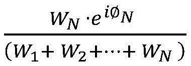
processing device 120 may determine the weighting coefficients based on the magnitude correction coefficients and/or the phase correction coefficients. For example, the correction factor may be calculated by, for example, a ratio between the amplitude correction factor and/or the phase correction factor corresponding to a particular set of imaging data and the sum of the amplitude correction factor and/or the phase correction factor corresponding to each set of imaging data in the at least two sets of imaging data (e.g.,
) A weighting factor corresponding to a particular set of imaging data is determined. In some embodiments, the weighting coefficients may include at least two weighting factors. Each of the at least two weighting factors may correspond toPixels of each of the at least two sets of imaging data. The value of the weighting factor may be positively correlated with a similarity between the pixels of each of the at least two sets of imaging data and the corresponding pixels of the reference imaging data. For example, the higher the similarity between the pixels of each of the at least two sets of imaging data and the corresponding pixels of the reference imaging data, the greater the value of the weighting factor corresponding to the pixels of each set of imaging data. More description about the similarity between two pixels can be found elsewhere in this application (e.g., fig. 7 and its description). In some embodiments, the weighting coefficients corresponding to some or all of the at least two sets of imaging data may be determined by a user or correspond to default settings of the
magnetic resonance system 100.
In some embodiments, the corrected at least two sets of imaging data may be in the k-space domain. For example, each of the at least two sets of corrected imaging data may include corrected k-space data. The corrected at least two sets of imaging data in the complex domain may be averaged according to equation (4) as follows:
wherein Y represents average imaging data, Y
NImaging data representing a particular set in the nth acquired k-space domain,
is represented by the formula
NCorresponding phase correction coefficients, F representing the Fourier transform, F
-1The inverse fourier transform is represented as,
representing a convolution operation, W
NIs represented by the formula
NThe corresponding amplitude correction factor. In some embodiments, the corrected at least two sets of imaging data may be in the k-space domain. For example, each of the at least two sets of corrected imaging data may include corrected k-space data. At least two sets of corrected k-space data can be performed in the k-space domainAveraged to obtain averaged k-space data.
In 550, the processing device 120 (e.g., the generation module 440) (e.g., the processor 210) may generate a target magnetic resonance image based on the averaged imaging data. The target magnetic resonance image may also be referred to as a diffusion image. In some embodiments, the processing device 120 may generate the target magnetic resonance image by converting the averaged imaging data of the k-space domain (i.e., the averaged k-space data) into averaged imaging data of the image domain. For example, the processing device 120 may perform a Fourier Transform (FT) on the averaged imaging data of the k-space domain. In some embodiments, the processing device 120 may designate the averaged imaging data in the image domain as the target magnetic resonance image.
It should be noted that the above description of process 500 is provided for illustrative purposes only and is not intended to limit the scope of the present application. Various changes and modifications will occur to those skilled in the art based on the description herein. However, such changes and modifications do not depart from the scope of the present application. In some embodiments, process 500 may include one or more additional operations, or may omit one or more of the operations described above. For example, operation 540 and operation 550 may be integrated into one operation. As another example, process 500 may include one or more additional operations (e.g., one or more operations of process 600) to determine one or more correction coefficients. In some embodiments, operation 530 and operation 540 may be integrated into one single operation. For example, as described elsewhere in this application, the average imaging data may be determined by weighting at least two sets of imaging data based on at least two weighting coefficients.
Fig. 6 is a flow chart illustrating an exemplary process for determining phase correction coefficients according to some embodiments of the present application. Process 600 may be performed by processing device 120. For example, the process 600 may be implemented as a set of instructions (e.g., an application program) stored in, for example, the memory 220, the storage device 130, the memory 390, a storage device externally accessible by the magnetic resonance system 100. Processing device 120, processor 210, and CPU340 may execute a set of instructions and, when executing the instructions, may be configured to perform process 600. The operations of process 600 presented below are intended to be illustrative. In some embodiments, the process may be accomplished with one or more additional operations not described and/or one or more operations not discussed. Additionally, the order in which the operations of process 600 are illustrated in FIG. 6 and described below is not intended to be limiting. At least a portion of operation 520 may be performed in accordance with process 600.
In 610, the processing device 120 (e.g., the correction module 420) (e.g., the processor 210) may determine one of the at least two sets of imaging data as the reference imaging data. At least two sets of imaging data may be acquired as described in connection with operation 510 described in fig. 5. Each of the at least two sets of imaging data may comprise a magnetic resonance image of the image domain. The magnetic resonance image may comprise at least two first pixels (or voxels). Each of the at least two first pixels (or voxels) may be represented by a first phase and a first magnitude in the complex domain.
In some embodiments, the processing device 120 may identify the one of the at least two sets of imaging data having the largest magnitude as the reference imaging data. For example, the processing device 120 may sum the first amplitude values of at least two first pixels (or voxels) in the magnetic resonance image corresponding to each of the at least two sets of imaging data. The processing device 120 may compare the sums of the first amplitudes corresponding to each of the at least two sets of imaging data to identify a maximum sum of the sums of the first amplitudes of the at least two sets of imaging data, and designate the set of imaging data corresponding to the maximum sum as reference imaging data. For another example, the processing device 120 may calculate an average of the first amplitude values of at least two first pixels (or voxels) in the magnetic resonance image corresponding to each of the at least two sets of imaging data. The processing device 120 may compare the average of the first amplitude values corresponding to each of the at least two sets of imaging data to identify a largest average of the first amplitude value averages of the at least two sets of imaging data and designate the set of imaging data corresponding to the largest average as reference imaging data.
In 620, the processing device 120 (e.g., the correction module 420) (e.g., the processor 210) may determine phase difference data between each of the at least two sets of imaging data and the reference imaging data. The reference imaging data may comprise a reference magnetic resonance image. The reference magnetic resonance image may comprise at least two second pixels (or voxels). Each of the at least two second pixels (or voxels) may be represented by a second phase and a second magnitude in the complex domain. The phase difference data between a particular set of the at least two sets of imaging data (i.e., a particular set of imaging data) and the reference imaging data may include at least two phase differences. Each of the at least two phase differences may comprise a difference between a phase of a first pixel (or voxel) in a particular set of imaging data (i.e. a particular magnetic resonance image) and a phase of a corresponding second pixel (or voxel) in reference imaging data (i.e. a reference image). As used herein, a first pixel (or voxel) in a particular set of imaging data corresponding to a second pixel (or voxel) in the reference imaging data may refer to the first pixel (or voxel) and the corresponding second pixel (or voxel) corresponding to the same spatial location of the object or the same location in the particular set of imaging data and the reference imaging data, respectively.
In some embodiments, a particular set of imaging data may be represented as a matrix (i.e., matrix a). The rows and columns of the matrix may represent the locations of at least two first pixels (or voxels) of a particular set of imaging data. Also, the values of the elements in the matrix a may represent the values of the first phases of at least two first pixels (or voxels) in the particular constituent image data. In some embodiments, the reference imaging data may be represented as another matrix (i.e., matrix B). The rows and columns of the matrix B may represent the locations of at least two second pixels (or voxels) of the reference imaging data. And, the values of the elements in the matrix B may represent the values of the second phases of at least two second pixels (or voxels) in the reference imaging data. The phase difference data of a specific set of imaging data may be generated by performing a subtraction operation between the matrix a and the matrix B.
In 630, the processing device 120 (e.g., the correction module 420) (e.g., the processor 210) may determine a phase correction coefficient corresponding to each of the at least two sets of imaging data based on the phase difference data. The phase correction coefficients corresponding to a particular set of imaging data may be represented by a phase correction matrix comprising at least two phase correction factors. Each of the at least two phase correction factors may correspond to one of the at least two first pixels (or voxels) in the particular set of imaging data.
In some embodiments, the processing device 120 may assign the phase difference data acquired in operation 620 as phase correction coefficients. In some embodiments, processing device 120 may perform a noise reduction operation on the phase difference data acquired in 620 to acquire noise reduced phase difference data. The processing device 120 may specify the noise-reduced phase difference data as a phase correction coefficient. Exemplary noise reduction operations may include the use of spatial domain filters, transform domain filters, morphological noise filters, and the like, or combinations thereof. For example, the spatial domain filter may include a gaussian mean filter, a median filter, a maximum filter, a minimum filter, and the like. The transform domain filter may include a low pass filter, a high pass filter, and the like.
In some embodiments, the process 600 may further include determining a weighting coefficient corresponding to each of the at least two sets of imaging data based on the phase correction coefficient. For example, the weighting coefficient corresponding to the imaging data of a particular group may be determined based on a ratio between the phase correction coefficient corresponding to the imaging data of the particular group and a sum of matrices of at least two groups of imaging data. In some embodiments, each matrix may correspond to one of the at least two sets of imaging data. Each matrix may include at least two elements, e.g., element values of 1.
It should be noted that the above description of process 500 is provided for illustrative purposes only and is not intended to limit the scope of the present application. Various changes and modifications will occur to those skilled in the art based on the description herein. However, such changes and modifications do not depart from the scope of the present application. For example, process 600 may further include an operation for denoising the phase difference data after operation 620.
FIG. 7 is a flow diagram illustrating an exemplary process for determining amplitude correction factors according to some embodiments of the present application. Process 700 may be performed by processing device 120. For example, the process 700 may be implemented as a set of instructions (e.g., an application program) stored in, for example, the memory 220, the storage device 130, the memory 390, a memory external to the magnetic resonance system 100 and accessible by the magnetic resonance system. Processing device 120, processor 210, and CPU340 may execute sets of instructions and, when executing the instructions, may be configured to perform process 700. The operations of process 700 presented below are intended to be illustrative. In some embodiments, the process may be accomplished with one or more additional operations not described and/or one or more operations not discussed. Additionally, the order in which the operations of process 700 are illustrated in FIG. 7 and described below is not intended to be limiting. At least a portion of operation 520 may be performed in accordance with process 700.
In 710, the processing device 120 (e.g., the correction module 420) (e.g., the processor 210) may determine one of the at least two sets of imaging data as the reference imaging data. At least two sets of imaging data may be acquired as described in connection with operation 510 described in fig. 5. Each of the at least two sets of imaging data may comprise a magnetic resonance image in an image domain. The magnetic resonance image may comprise at least two first pixels (or voxels). Each of the at least two first pixels (or voxels) may be represented by a first phase and a first magnitude in the complex domain. In some embodiments, the processing device 120 may identify the one of the at least two sets of imaging data having the largest magnitude as the reference imaging data. For example, the processing device 120 may calculate a sum of the first amplitude values of at least two first pixels (or voxels) in the magnetic resonance image corresponding to each of the at least two sets of imaging data. The processing device 120 may compare the sums of the first amplitudes corresponding to each of the at least two sets of imaging data to identify a maximum sum of the sums of the first amplitudes in the at least two sets of imaging data, and designate the set of imaging data corresponding to the maximum sum as reference imaging data. For another example, the processing device 120 may calculate an average of the first amplitude values of at least two first pixels (or voxels) in the magnetic resonance image corresponding to each of the at least two sets of imaging data. The processing device 120 may compare the average of the first amplitude values of at least two first pixels (or voxels) in the magnetic resonance image corresponding to each of the at least two sets of imaging data to identify a largest average of the first amplitude values in the at least two sets of imaging data, and designate the set of imaging data corresponding to the largest average as reference imaging data.
In some embodiments, the processing device 120 may determine an average of the magnitude data associated with the at least two sets of imaging data and designate the average of the magnitude data associated with the at least two sets of imaging data as the reference imaging data. Specifically, each of the at least two sets of imaging data may be represented as a matrix. The rows and columns of the matrix may represent the locations of at least two first pixels (or voxels) of each of the at least two sets of imaging data. And the values of the elements in the matrix may represent values of first magnitudes of at least two first pixels (or voxels) of each of the at least two sets of imaging data. The processing device 120 may acquire the magnitude data associated with the at least two sets of imaging data by performing an addition operation on matrices corresponding to the at least two sets of imaging data. The processing device 120 may further determine an average of the magnitude data. Then, the processing device 120 may designate an average of the magnitude data associated with the at least two sets of imaging data as the reference imaging data.
In 720, the processing device 120 (e.g., the correction module 420) (e.g., the processor 210) may determine similar data between each of the at least two sets of imaging data and the reference imaging data. The reference imaging data may comprise a reference magnetic resonance image. The reference magnetic resonance image may comprise at least two second pixels (or voxels). Each of the at least two second pixels (or voxels) may be represented by a second phase and a second magnitude in the complex domain. The similar data between a particular set of the at least two sets of imaging data (i.e., the particular set of imaging data) and the reference imaging data may include at least two similar elements. Each of the at least two similar elements may correspond to a first pixel (or voxel) in a particular set of imaging data (i.e., a particular magnetic resonance image) and a corresponding second pixel (or voxel) in reference imaging data (i.e., a reference image). Each of the at least two similar elements may represent a similarity between a first pixel (or voxel) in a particular set of imaging data (i.e., a particular magnetic resonance image) and a corresponding second pixel (or voxel) in reference imaging data (i.e., a reference image). As used herein, a first pixel (or voxel) in a particular set of imaging data corresponding to a second pixel (or voxel) in the reference imaging data may refer to the first pixel (or voxel) and the corresponding second pixel (or voxel) corresponding to the same spatial location or portion of the object or the same location in the particular set of imaging data and the reference imaging data, respectively.
In some embodiments, similarity data between a particular set of the at least two sets of imaging data and the reference imaging data may be determined in the image domain. For example, a similar element between a first pixel (or voxel) in a particular set of imaging data (i.e., a particular magnetic resonance image) and a corresponding second pixel (or voxel) in the reference imaging data (i.e., a reference image) may be determined based on pixel (or voxel) values of the first pixel (or voxel) in the particular set of imaging data (i.e., the particular magnetic resonance image) and the corresponding second pixel (or voxel) in the reference imaging data (i.e., the reference image). Processing device 120 may compare the values of the pixels (or voxels) of the first pixel (or voxel) and the corresponding second pixel (or voxel). The smaller the difference between the values of the pixels (or voxels) of a first pixel (or voxel) and a corresponding second pixel (or voxel), the larger the similarity element between the first pixel (or voxel) and the corresponding second pixel (or voxel).
In some embodiments, the processing device 120 may determine similar data in the magnitude domain between each of the at least two sets of imaging data and the reference imaging data. For example, the processing device 120 may determine similar data between a particular set of imaging data and reference imaging data based on magnitude difference data between the particular set of imaging data and the reference imaging data. The magnitude difference data between the particular set of imaging data and the reference imaging data may include at least two magnitude differences. Each of the at least two amplitude differences may correspond to a first pixel (or voxel) in a particular set of imaging data (i.e., a particular magnetic resonance image) and a corresponding second pixel (or voxel) in the reference imaging data (i.e., a reference image). For another example, processing device 120 may compare the magnitude of a first pixel (or voxel) and a corresponding second pixel (or voxel) to determine a difference in magnitude of the first pixel (or voxel) relative to the corresponding second pixel (or voxel). Processing device 120 may determine similar elements of a first pixel (or voxel) relative to a corresponding second pixel (or voxel) based on a magnitude difference between the first pixel (or voxel) and the corresponding second pixel (or voxel). The smaller the magnitude difference between a first pixel (or voxel) and a corresponding second pixel (or voxel), the larger the similar elements of the first pixel (or voxel) relative to the corresponding second pixel (or voxel).
In some embodiments, processing device 120 may perform a noise reduction operation on the magnitude difference data to obtain noise reduced magnitude difference data. Processing device 120 may determine similar data based on the noise-reduced magnitude difference data. Exemplary noise reduction operations may include the use of spatial domain filters, transform domain filters, morphological noise filters, and the like, or combinations thereof. For example, the spatial domain filter may include a gaussian mean filter, a median filter, a maximum filter, a minimum filter, and the like. The transform domain filter may include a low pass filter, a high pass filter, and the like.
In 730, the processing device 120 (e.g., the correction module 420) (e.g., the processor 210) may determine a magnitude correction coefficient corresponding to each of the at least two sets of imaging data based on the similar data. The amplitude correction factor corresponding to a particular set of imaging data may be represented by an amplitude correction matrix comprising at least two amplitude correction factors. Each of the at least two magnitude correction factors may correspond to one of at least two first pixels (or voxels) of the particular set of imaging data.
In some embodiments, the similar data between the particular set of imaging data and the reference imaging data may include at least two similar elements. Each of the at least two similar elements may correspond to a first pixel (or voxel) of a particular set of imaging data. Processing device 120 may determine the magnitude correction factor corresponding to the first pixel (or voxel) in the particular set of imaging data based on the similar element corresponding to the first pixel (or voxel) in the particular set of imaging data. The larger the similar element corresponding to the first pixel (or voxel), the larger the magnitude correction factor corresponding to the first pixel (or voxel). In some embodiments, processing device 120 may perform a noise reduction operation on the similar data to obtain noise reduced similar data. Processing device 120 may determine the amplitude correction factor based on the noise-reduced similar data.
In some embodiments, the process 700 may further include determining a weighting coefficient corresponding to each of the at least two sets of imaging data based on the magnitude correction coefficient. For example, the weighting coefficient corresponding to the imaging data of a particular group may be determined based on a ratio between the amplitude correction coefficient corresponding to the imaging data of the particular group and the sum of the amplitude correction coefficients corresponding to the at least two groups of imaging data.
It should be noted that the above description of process 500 is provided for illustrative purposes only and is not intended to limit the scope of the present application. Various changes and modifications will occur to those skilled in the art based on the description herein. However, such changes and modifications do not depart from the scope of the present application. For example, process 700 may include performing a noise reduction operation on similar data after operation 720.
Examples of the invention
These examples are provided for illustrative purposes and are not intended to limit the scope of the present application.
Example 1 exemplary magnetic resonance brain image of a patient
Fig. 8 is an MR brain image of a patient shown according to some embodiments of the present application. As shown in fig. 8, image 1 and image 2 were reconstructed based on the same imaging data, which was acquired by performing 10 Echo Planar Imaging (EPI) sequences. The imaging data used to reconstruct image 1 and image 2 corresponds to a diffusion sensitivity coefficient (i.e., b-value) of 10000, which is determined based on the diffusion gradient. The higher the b-value, the smaller the SNR may be, and the greater the contrast between different types of tissues may be. Image 1 is reconstructed based on an averaging algorithm in the magnitude domain. Image 2 was reconstructed according to process 500 described in fig. 5. Image 1, for example, in area a, displays more noise than image 2. In other words, the signal-to-noise ratio (SNR) of image 2 exceeds the signal-to-noise ratio of image 1.
Example 2 exemplary magnetic resonance prostate image of a patient
Fig. 9 is an MR prostate image of a patient shown according to some embodiments of the present application. As shown in fig. 9, image 1 and image 2 were reconstructed based on the same imaging data, which was acquired by performing an Echo Planar Imaging (EPI) sequence of 12 times. The imaging data used to reconstruct image 1 and image 2 corresponds to a diffusion sensitivity coefficient (i.e., b-value) of 1500, determined based on the diffusion gradient. Image 1, for example, in region B, displays more noise than image 2. In other words, the signal-to-noise ratio (SNR) of image 2 exceeds the signal-to-noise ratio of image 1. According to fig. 8 and 9, the method for diffusion magnetic resonance imaging described elsewhere in this application (e.g., fig. 5 and its description) can reduce noise to improve the SNR of the diffusion magnetic resonance image, and can improve image quality even if the b value is high.
Having thus described the basic concepts, it will be apparent to those of ordinary skill in the art having read this application that the foregoing disclosure is to be construed as illustrative only and is not limiting of the application. Various modifications, improvements and adaptations of the present application may occur to those skilled in the art, although they are not explicitly described herein. Such modifications, improvements and adaptations are proposed in the present application and thus fall within the spirit and scope of the exemplary embodiments of the present application.
Also, this application uses specific language to describe embodiments of the application. For example, the terms "one embodiment," "an embodiment," and/or "some embodiments" mean that a particular feature, structure, or characteristic described in connection with the embodiment is included in at least one embodiment of the present application. Therefore, it is emphasized and should be appreciated that two or more references to "an embodiment" or "one embodiment" or "an alternative embodiment" in various places throughout this specification are not necessarily all referring to the same embodiment. Furthermore, the particular features, structures, or characteristics may be combined as suitable in one or more embodiments of the application.
Moreover, those of ordinary skill in the art will understand that aspects of the present application may be illustrated and described in terms of several patentable species or situations, including any new and useful combination of processes, machines, articles, or materials, or any new and useful improvement thereof. Accordingly, aspects of the present application may be embodied entirely in hardware, entirely in software (including firmware, resident software, micro-code, etc.), or in a combination of software and hardware, all generally referred to herein as a "unit," module, "or" system. Furthermore, aspects of the present application may take the form of a computer program product embodied in one or more computer-readable media having computer-readable program code embodied therein.
A computer readable signal medium may contain a propagated data signal with computer program code embodied therewith, for example, in baseband or as part of a carrier wave. Such a propagated signal may take any of a variety of forms, including electro-magnetic, optical, and the like, or any suitable combination. A computer readable signal medium may be any computer readable medium that is not a computer readable storage medium and that can communicate, propagate, or transport a program for use by or in connection with an instruction execution system, apparatus, or device. Program code on a computer readable signal medium may be propagated over any suitable medium, including radio, cable, fiber optic cable, RF, etc., or any combination of the preceding.
Computer program code for carrying out operations for aspects of the present application may be written in any combination of one or more programming languages, including an object oriented programming language such as Java, Scala, Smalltalk, Eiffel, JADE, Emerald, C + +, C #, VB, NET, Python, etc., a conventional programming language such as the "C" programming language, Visual Basic, Fortran2003, Perl, COBOL2002, PHP, ABAP, a dynamic programming language such as Python, Ruby and Groovy, or other programming languages. The program code may execute entirely on the user's computer, partly on the user's computer, as a stand-alone software package, partly on the user's computer and partly on a remote computer or entirely on the remote computer or server. In the latter scenario, the remote computer may be connected to the user's computer through any type of network, including a Local Area Network (LAN) or a Wide Area Network (WAN), or the connection may be made to an external computer (for example, through the use of a network service provider's network) or provided in a cloud computing environment or as a service, such as a software service (SaaS).
Additionally, the order in which elements and sequences of the processes described herein are processed, the use of alphanumeric characters, or the use of other designations, is not intended to limit the order of the processes and methods described herein, unless explicitly claimed. While various presently contemplated embodiments of the invention have been discussed in the foregoing disclosure by way of example, it is to be understood that such detail is solely for that purpose and that the appended claims are not limited to the disclosed embodiments, but, on the contrary, are intended to cover all modifications and equivalent arrangements that are within the spirit and scope of the embodiments herein. For example, although implementations of the various components described above may be embodied in a hardware device, they may also be implemented as a pure software solution, e.g., installation on an existing server or mobile device.
Similarly, it should be noted that in the preceding description of embodiments of the application, various features are sometimes grouped together in a single embodiment, figure, or description thereof for the purpose of streamlining the disclosure aiding in the understanding of one or more embodiments of the invention. This method of application, however, is not to be interpreted as reflecting an intention that the claimed subject matter to be scanned requires more features than are expressly recited in each claim. Indeed, the embodiments may be characterized as having less than all of the features of a single embodiment disclosed above.