[go: up one dir, main page]

CN112698416B - Gravitational acceleration measuring method and system suitable for strapdown inertial navigation system - Google Patents

Gravitational acceleration measuring method and system suitable for strapdown inertial navigation system Download PDF

Info

Publication number
CN112698416B
CN112698416B CN202011486204.2A CN202011486204A CN112698416B CN 112698416 B CN112698416 B CN 112698416B CN 202011486204 A CN202011486204 A CN 202011486204A CN 112698416 B CN112698416 B CN 112698416B
Authority
CN
China
Prior art keywords
direction accelerometer
accelerometer
acceleration
coordinate system
raw data
Prior art date
Legal status (The legal status is an assumption and is not a legal conclusion. Google has not performed a legal analysis and makes no representation as to the accuracy of the status listed.)
Active
Application number
CN202011486204.2A
Other languages
Chinese (zh)
Other versions
CN112698416A (en
Inventor
刘兆梅
曾浩瀚
李永满
刘秀敏
Current Assignee (The listed assignees may be inaccurate. Google has not performed a legal analysis and makes no representation or warranty as to the accuracy of the list.)
Hunan Aerospace Institute of Mechanical and Electrical Equipment and Special Materials
Original Assignee
Hunan Aerospace Institute of Mechanical and Electrical Equipment and Special Materials
Priority date (The priority date is an assumption and is not a legal conclusion. Google has not performed a legal analysis and makes no representation as to the accuracy of the date listed.)
Filing date
Publication date
Application filed by Hunan Aerospace Institute of Mechanical and Electrical Equipment and Special Materials filed Critical Hunan Aerospace Institute of Mechanical and Electrical Equipment and Special Materials
Priority to CN202011486204.2A priority Critical patent/CN112698416B/en
Publication of CN112698416A publication Critical patent/CN112698416A/en
Application granted granted Critical
Publication of CN112698416B publication Critical patent/CN112698416B/en
Active legal-status Critical Current
Anticipated expiration legal-status Critical

Links

Images

Classifications

    • GPHYSICS
    • G01MEASURING; TESTING
    • G01VGEOPHYSICS; GRAVITATIONAL MEASUREMENTS; DETECTING MASSES OR OBJECTS; TAGS
    • G01V7/00Measuring gravitational fields or waves; Gravimetric prospecting or detecting
    • GPHYSICS
    • G01MEASURING; TESTING
    • G01CMEASURING DISTANCES, LEVELS OR BEARINGS; SURVEYING; NAVIGATION; GYROSCOPIC INSTRUMENTS; PHOTOGRAMMETRY OR VIDEOGRAMMETRY
    • G01C21/00Navigation; Navigational instruments not provided for in groups G01C1/00 - G01C19/00
    • G01C21/10Navigation; Navigational instruments not provided for in groups G01C1/00 - G01C19/00 by using measurements of speed or acceleration
    • G01C21/12Navigation; Navigational instruments not provided for in groups G01C1/00 - G01C19/00 by using measurements of speed or acceleration executed aboard the object being navigated; Dead reckoning
    • G01C21/16Navigation; Navigational instruments not provided for in groups G01C1/00 - G01C19/00 by using measurements of speed or acceleration executed aboard the object being navigated; Dead reckoning by integrating acceleration or speed, i.e. inertial navigation
    • G01C21/18Stabilised platforms, e.g. by gyroscope

Landscapes

  • Engineering & Computer Science (AREA)
  • Radar, Positioning & Navigation (AREA)
  • Remote Sensing (AREA)
  • Physics & Mathematics (AREA)
  • General Physics & Mathematics (AREA)
  • Automation & Control Theory (AREA)
  • Life Sciences & Earth Sciences (AREA)
  • General Life Sciences & Earth Sciences (AREA)
  • Geophysics (AREA)
  • Navigation (AREA)

Abstract

The invention discloses a gravitational acceleration measuring method and a system suitable for a strapdown inertial navigation system, wherein the gravitational acceleration measuring method comprises the following steps: step 1, rotating an indexing mechanism to a first position; step 2, under the static measurement condition, sampling the X-direction accelerometer, the Y-direction accelerometer and the Z-direction accelerometer to obtain n of the first position1Original data; step 3, rotating the indexing mechanism for 180 degrees around the horizontal shaft to a second position; step 4, under the condition of static measurement, sampling the X-direction accelerometer, the Y-direction accelerometer and the Z-direction accelerometer to obtain n of a second position2Original data; and 5, calculating based on the original data obtained in the step 2 and the step 4, and outputting a gravity acceleration value g. The invention utilizes the indexing mechanism embedded in the strapdown inertial navigation system, static acquisition is carried out at two positions with 180-degree difference, and the gravity acceleration measurement error introduced by the accelerometer is eliminated through calculation, so that a high-precision gravity acceleration measurement result is obtained, and the measurement process is simple.

Description

Gravitational acceleration measuring method and system suitable for strapdown inertial navigation system
Technical Field
The invention belongs to the technical field of gravity acceleration measurement, and particularly relates to a gravity acceleration measurement method and system suitable for a strapdown inertial navigation system.
Background
The earth gravity field data is an important strategic resource of the country and has very important functions in the fields of national defense and military technologies, space technologies, resource exploration, geophysical research and geodetic survey.
The measurement of the gravitational acceleration is generally implemented using a gravimeter or a gravity measurement system, and the core device of the gravimeter or the gravity measurement system is a gravity sensor. An accelerometer, as an inertial device, can sense acceleration relative to an inertial space, and as an important gravity sensor, the accelerometer is widely applied to gravity acceleration measurement equipment.
The strapdown inertial navigation system is used as an inertial measurement device, and the core devices are a gyroscope and an accelerometer. The strapdown inertial navigation system is provided with three accelerometers, namely an X-direction accelerometer, a Y-direction accelerometer and a Z-direction accelerometer, wherein the X-direction accelerometer is arranged in the X direction of an acceleration coordinate system, the Y-direction accelerometer is arranged in the Y direction of the acceleration coordinate system, the Z-direction accelerometer is arranged in the Z direction of the acceleration coordinate system, and the acceleration coordinate system meets the right-hand rule. In a static environment, three accelerometers sense gravity acceleration information, and the output of the accelerometers is subjected to parameter correction to obtain a gravity acceleration value. Therefore, the gravity acceleration measuring function can be realized on the strapdown inertial navigation system.
In the strapdown inertial navigation system, the precision of the selected accelerometer is generally determined according to the precision index of the system, and the precision requirement of gravity acceleration measurement is generally not considered, so that the gravity acceleration obtained by the strapdown inertial navigation system is low in precision.
Disclosure of Invention
The invention aims to provide a gravity acceleration measurement method and system suitable for a strapdown inertial navigation system, aiming at the defect of low gravity acceleration precision obtained by the strapdown inertial navigation system in the prior art, and the gravity acceleration measurement result with high precision can be obtained.
In order to solve the technical problems, the technical scheme adopted by the invention is as follows:
a gravity acceleration measuring method suitable for a strapdown inertial navigation system is provided with an X-direction accelerometer, a Y-direction accelerometer and a Z-direction accelerometer, wherein the X-direction accelerometer, the Y-direction accelerometer and the Z-direction accelerometer are respectively and correspondingly arranged in the X direction, the Y direction and the Z direction of an acceleration coordinate system, and the acceleration coordinate system meets the right-hand rule; the X-direction accelerometer, the Y-direction accelerometer and the Z-direction accelerometer are all arranged on the indexing mechanism; the method is characterized by comprising the following steps:
step 1, rotating an indexing mechanism to a first position;
step 2, under the condition of static measurement, sampling the X-direction accelerometer, the Y-direction accelerometer and the Z-direction accelerometer to obtain n of a first position1Raw data, wherein the sampling interval at the first position is Δ t1
Step 3, rotating the indexing mechanism by 180 degrees around a horizontal shaft to a second position;
step 4, under the condition of static measurement, sampling the X-direction accelerometer, the Y-direction accelerometer and the Z-direction accelerometer to obtain n of a second position2Raw data, wherein the sampling interval at the second position is Δ t2
And 5, calculating based on the original data obtained in the step 2 and the step 4, and outputting a gravity acceleration value g.
By means of the scheme, the static acquisition is carried out at two positions with a 180-degree difference by using the indexing mechanism embedded in the strapdown inertial navigation system, and the gravity acceleration measurement error introduced by the accelerometer can be eliminated through calculation, so that a high-precision gravity acceleration measurement result can be obtained.
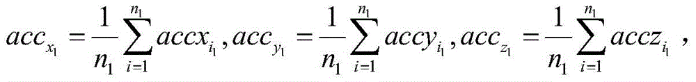
In a preferable mode, in the step 5,
Figure BDA0002839425490000021
Figure BDA0002839425490000022
Figure BDA0002839425490000023
Figure BDA0002839425490000024
kzx is a mounting error of an X-direction accelerometer relative to a Z axis of an acceleration coordinate system, Kyx is a mounting error of the X-direction accelerometer relative to a Y axis of the acceleration coordinate system, Kzy is a mounting error of the Y-direction accelerometer relative to a Z axis of the acceleration coordinate system, Kxy is a mounting error of the Y-direction accelerometer relative to an X axis of the acceleration coordinate system, Kyz is a mounting error of the Z-direction accelerometer relative to a Y axis of the acceleration coordinate system, Kxz is a mounting error of the Z-direction accelerometer relative to an X axis of the acceleration coordinate system, K1X is a scaling factor of the X-direction accelerometer, K1Y is a scaling factor of the Y-direction accelerometer, K1Z is a scaling factor of the Z-direction accelerometer, K0X is a zero offset of the X-direction accelerometer, K0Y is a zero offset of the Y-direction accelerometer, and K0Z is a zero offset of the Z-direction accelerometer;
Figure BDA0002839425490000031
Figure BDA0002839425490000032
for the ith raw data acquired by the X-direction accelerometer at the first location,
Figure BDA0002839425490000033
for the ith raw data acquired by the Y-direction accelerometer at the first location,
Figure BDA0002839425490000034
acquiring ith raw data at a first position for the Z-direction accelerometer;
Figure BDA0002839425490000035
Figure BDA0002839425490000036
for the ith raw data acquired by the X-direction accelerometer at the second location,
Figure BDA0002839425490000037
is YTo the ith raw data acquired by the accelerometer at the second location,
Figure BDA0002839425490000038
the ith raw data collected for the Z-direction accelerometer at the second location.
By means of the method, calibration parameter compensation is carried out on the output of the accelerometer, then the gravity acceleration values of the first position and the second position are obtained, and finally the final gravity acceleration value g is obtained by averaging the calculation results of the two positions.
Further, in the step 1, the indexing mechanism is locked after the indexing mechanism rotates to the first position; in the step 3, the indexing mechanism is unlocked and then rotated, and is locked after the indexing mechanism rotates to the second position.
Preferably, the first position is an skyward position or a geodetic position of the strapdown inertial navigation system.
Static acquisition is carried out at two positions with a difference of 180 degrees between the sky position and the earth position, and the measurement error of the accelerometer is eliminated through calculation, so that the effect is optimal.
Based on the same invention concept, the invention also provides a gravity acceleration measuring system suitable for the strapdown inertial navigation system, wherein the strapdown inertial navigation system is provided with a controller, a control circuit, an X-direction accelerometer, a Y-direction accelerometer and a Z-direction accelerometer, the X-direction accelerometer, the Y-direction accelerometer and the Z-direction accelerometer are respectively and correspondingly arranged in the X direction, the Y direction and the Z direction of an acceleration coordinate system, and the acceleration coordinate system meets the right-hand rule; the X-direction accelerometer, the Y-direction accelerometer and the Z-direction accelerometer are all arranged on the indexing mechanism; the controller is connected with the indexing mechanism through the control circuit and is used for controlling whether the indexing mechanism rotates or not through the control circuit; the controller is characterized by also comprising a storage unit and an output unit, wherein a computing unit is arranged in the controller; wherein:
the X-direction accelerometer, the Y-direction accelerometer and the Z-direction accelerometer are all used for obtaining samples under the condition of static measurement when the indexing mechanism is at the first positionN is obtained at the first position1The raw data is sent to the controller corresponding to the first position, wherein the sampling interval time at the first position is delta t1(ii) a The X-direction accelerometer, the Y-direction accelerometer and the Z-direction accelerometer are all used for obtaining n of the second position by sampling under the condition of static measurement when the indexing mechanism is at the second position2The raw data is sent to the controller corresponding to the second position, where the sampling interval is Δ t2(ii) a The rotating mechanism rotates 180 degrees around the horizontal shaft by taking the first position as a starting point and then reaches a second position;
a storage unit: the device comprises a storage controller, a first storage unit, a second storage unit and a controller, wherein the storage controller is used for storing original data corresponding to a first position and original data corresponding to a second position which are sent by the controller;
a calculation unit: the gravity acceleration sensor is used for calculating based on the original data corresponding to the first position and the original data corresponding to the second position to obtain a gravity acceleration value g;
an output unit: for outputting a gravitational acceleration value g.
As a preferable mode, the calculation unit obtains the gravitational acceleration value g by calculating:
Figure BDA0002839425490000041
Figure BDA0002839425490000042
Figure BDA0002839425490000043
Figure BDA0002839425490000044
wherein Kzx is the installation error of the X-direction accelerometer relative to the Z axis of the acceleration coordinate system, Kyx is the installation error of the X-direction accelerometer relative to the Y axis of the acceleration coordinate systemKzy is a mounting error of the Y-direction accelerometer relative to a Z axis of an acceleration coordinate system, Kxy is a mounting error of the Y-direction accelerometer relative to an X axis of the acceleration coordinate system, Kyz is a mounting error of the Z-direction accelerometer relative to a Y axis of the acceleration coordinate system, Kxz is a mounting error of the Z-direction accelerometer relative to an X axis of the acceleration coordinate system, K1X is a scale factor of the X-direction accelerometer, K1Y is a scale factor of the Y-direction accelerometer, K1Z is a scale factor of the Z-direction accelerometer, K0X is a zero offset of the X-direction accelerometer, K0Y is a zero offset of the Y-direction accelerometer, and K0Z is a zero offset of the Z-direction accelerometer;
Figure BDA0002839425490000051
Figure BDA0002839425490000052
for the ith raw data acquired by the X-direction accelerometer at the first location,
Figure BDA0002839425490000053
for the ith raw data acquired by the Y-direction accelerometer at the first location,
Figure BDA0002839425490000054
acquiring ith raw data at a first position for the Z-direction accelerometer;
Figure BDA0002839425490000055
Figure BDA0002839425490000056
for the ith raw data acquired by the X-direction accelerometer at the second location,
Figure BDA0002839425490000057
for the ith raw data acquired by the Y-direction accelerometer at the second position,
Figure BDA0002839425490000058
the ith raw data collected for the Z-direction accelerometer at the second location.
The indexing mechanism further comprises a locking mechanism, the controller is electrically connected with a control end of the locking mechanism, and the controller is used for locking or unlocking the indexing mechanism through the locking mechanism.
Preferably, the first position is an skyward position or a geodetic position of the strapdown inertial navigation system.
Compared with the prior art, the method utilizes the indexing mechanism embedded in the strapdown inertial navigation system, static acquisition is carried out at two positions with a 180-degree difference, and the gravity acceleration measurement error introduced by the accelerometer is eliminated through calculation, so that a high-precision gravity acceleration measurement result is obtained, and the measurement process is simple.
Drawings
FIG. 1 is a flow chart of the measurement method of the present invention.
FIG. 2 is a schematic diagram of the system of the present invention.
The system comprises a controller 1, a computing unit 101, a control circuit 2, an indexing mechanism 3, an X-direction accelerometer 4, a Y-direction accelerometer 5, a Z-direction accelerometer 6, a storage unit 7, an output unit 8 and a locking mechanism 9.
Detailed Description
The strapdown inertial navigation system applicable to the invention is provided with three accelerometers, namely an X-direction accelerometer 4, a Y-direction accelerometer 5 and a Z-direction accelerometer 6, wherein the X-direction accelerometer 4 is arranged in the X direction of an acceleration coordinate system, the Y-direction accelerometer 5 is arranged in the Y direction of the acceleration coordinate system, the Z-direction accelerometer 6 is arranged in the Z direction of the acceleration coordinate system, and the acceleration coordinate system meets the right-hand rule; the X-direction accelerometer 4, the Y-direction accelerometer 5 and the Z-direction accelerometer 6 are all arranged on the indexing mechanism 3.
As shown in fig. 1, the method for measuring gravitational acceleration applicable to a strapdown inertial navigation system according to the present invention includes the following steps:
step 1, rotating an indexing mechanism 3 to a first position, and locking the indexing mechanism 3;
step 2, measuring for 30s under a static measurement condition, sampling an X-direction accelerometer 4, a Y-direction accelerometer 5 and a Z-direction accelerometer 6 to obtain 30 original data of a first position, wherein the sampling interval time at the first position is 1 s; the first position is an sky position or a ground position of the strapdown inertial navigation system;
step 3, after the indexing mechanism 3 is unlocked, the indexing mechanism 3 rotates 180 degrees around the horizontal shaft to a second position, and the indexing mechanism 3 is locked;
step 4, measuring for 30s under a static measurement condition, and sampling the X-direction accelerometer 4, the Y-direction accelerometer 5 and the Z-direction accelerometer 6 to obtain 30 original data of a second position, wherein the sampling interval time at the second position is 1 s;
and 5, calculating based on the original data obtained in the step 2 and the step 4, and outputting a gravity acceleration value g.
The invention utilizes the indexing mechanism 3 embedded in the strapdown inertial navigation system to perform static acquisition at two positions with a difference of 180 degrees between the zenith position and the geodetic position, and eliminates the gravity acceleration measurement error introduced by the accelerometer through calculation, thereby obtaining a high-precision gravity acceleration measurement result.
In step 5, the gravity acceleration value g is calculated by the following formula:
Figure BDA0002839425490000061
Figure BDA0002839425490000062
Figure BDA0002839425490000063
Figure BDA0002839425490000071
wherein Kzx is the installation error of the X-direction accelerometer 4 relative to the Z axis of the acceleration coordinate system, Kyx is the installation error of the X-direction accelerometer 4 relative to the Y axis of the acceleration coordinate system, Kzy is the installation error of the Y-direction accelerometer 5 relative to the Z axis of the acceleration coordinate system, Kxy is the installation error of the Y-direction accelerometer 5 relative to the acceleration coordinate systemMounting error of an X axis, Kyz is mounting error of the Z-direction accelerometer 6 relative to a Y axis of an acceleration coordinate system, Kxz is mounting error of the Z-direction accelerometer 6 relative to the X axis of the acceleration coordinate system, K1X is a scale factor of the X-direction accelerometer 4, K1Y is a scale factor of the Y-direction accelerometer 5, K1Z is a scale factor of the Z-direction accelerometer 6, K0X is zero offset of the X-direction accelerometer 4, K0Y is zero offset of the Y-direction accelerometer 5, and K0Z is zero offset of the Z-direction accelerometer 6;
Figure BDA0002839425490000072
Figure BDA0002839425490000073
for the ith raw data acquired by the X-direction accelerometer 4 at the first location,
Figure BDA0002839425490000074
for the ith raw data acquired by the Y-direction accelerometer 5 at the first position,
Figure BDA0002839425490000075
the ith raw data collected at the first position for the Z-direction accelerometer 6;
Figure BDA0002839425490000076
Figure BDA0002839425490000077
for the ith raw data acquired by the X-direction accelerometer 4 at the second location,
Figure BDA0002839425490000078
for the ith raw data acquired by the Y-direction accelerometer 5 at the second position,
Figure BDA0002839425490000079
the ith raw data collected at the second position for the Z-direction accelerometer 6. n is1For the total number of sample points of each accelerometer at a first position, n2For the total number of sample points of the accelerometer at the second position, n in the embodiment1And n2Are all 30. Δ t1Is the sampling interval time at the first position, Δ t2Is the sampling interval time at the second position, Δ t in the example1And Δ t2Are all 1 s.
According to the invention, calibration parameter compensation is firstly carried out on the output of the accelerometer, then the gravity acceleration values at the first position and the second position are obtained, and finally the final gravity acceleration value g is obtained by taking the average value of the calculation results of the two positions.
As shown in fig. 2, the present invention further provides a gravitational acceleration measurement system suitable for a strapdown inertial navigation system, wherein the strapdown inertial navigation system is further provided with a controller 1 and a control circuit 2; the controller 1 is connected with the indexing mechanism 3 through the control circuit 2, and the controller 1 is used for controlling whether the indexing mechanism 3 rotates or not through the control circuit 2. The gravity acceleration measuring system further comprises a locking mechanism 9, the controller 1 is electrically connected with a control end of the locking mechanism 9, and the controller 1 is used for locking or unlocking the indexing mechanism 3 through the locking mechanism 9.
The gravity acceleration measuring system suitable for the strapdown inertial navigation system further comprises a storage unit 7 and an output unit 8, and a calculating unit 101 is arranged in the controller 1; wherein:
the X-direction accelerometer 4, the Y-direction accelerometer 5 and the Z-direction accelerometer 6 are all used for obtaining n of a first position by sampling under the static measurement condition when the indexing mechanism 3 is at the first position1The raw data is sent to the controller 1 corresponding to the first position where the sampling interval is Δ t1(ii) a The X-direction accelerometer 4, the Y-direction accelerometer 5 and the Z-direction accelerometer 6 are all used for obtaining n of the second position by sampling under the static measurement condition when the indexing mechanism 3 is at the second position2The raw data is sent to the controller 1 corresponding to the second position with a sampling interval Δ t2(ii) a The rotating mechanism rotates 180 degrees around the horizontal shaft by taking the first position as a starting point and then reaches a second position; preferably, the first position is a sky position or a ground position of the strapdown inertial navigation system.
The storage unit 7: the data storage device is used for storing original data corresponding to a first position and original data corresponding to a second position which are sent by the controller 1;
the calculation unit 101: the gravity acceleration sensor is used for calculating based on the original data corresponding to the first position and the original data corresponding to the second position to obtain a gravity acceleration value g;
the output unit 8: for outputting a gravitational acceleration value g.
The calculation unit 101 obtains the gravitational acceleration value g by calculating:
Figure BDA0002839425490000081
Figure BDA0002839425490000082
Figure BDA0002839425490000083
Figure BDA0002839425490000091
kzx is a mounting error of the X-direction accelerometer 4 relative to a Z axis of an acceleration coordinate system, Kyx is a mounting error of the X-direction accelerometer 4 relative to a Y axis of the acceleration coordinate system, Kzy is a mounting error of the Y-direction accelerometer 5 relative to a Z axis of the acceleration coordinate system, Kxy is a mounting error of the Y-direction accelerometer 5 relative to an X axis of the acceleration coordinate system, Kyz is a mounting error of the Z-direction accelerometer 6 relative to a Y axis of the acceleration coordinate system, Kxz is a mounting error of the Z-direction accelerometer 6 relative to an X axis of the acceleration coordinate system, K1X is a scale factor of the X-direction accelerometer 4, K1Y is a scale factor of the Y-direction accelerometer 5, K1Z is a scale factor of the Z-direction accelerometer 6, K0X is a zero offset of the X-direction accelerometer 4, K0Y is a zero offset of the Y-direction accelerometer 5, and K0Z is a zero offset of the Z-direction accelerometer 6;
Figure BDA0002839425490000092
Figure BDA0002839425490000093
for the ith raw data acquired by the X-direction accelerometer 4 at the first location,
Figure BDA0002839425490000094
for the ith raw data acquired by the Y-direction accelerometer 5 at the first position,
Figure BDA0002839425490000095
the ith raw data collected at the first position for the Z-direction accelerometer 6;
Figure BDA0002839425490000096
Figure BDA0002839425490000097
for the ith raw data acquired by the X-direction accelerometer 4 at the second location,
Figure BDA0002839425490000098
for the ith raw data acquired by the Y-direction accelerometer 5 at the second position,
Figure BDA0002839425490000099
the ith raw data collected at the second position for the Z-direction accelerometer 6.
In order to verify the measurement effect of the gravity acceleration, the invention utilizes a certain laser strapdown inertial unit system to carry out experimental verification, and the precision indexes of an accelerometer in the strapdown inertial unit system are as follows: the null stability was better than 100ug (3 σ, one year) and the scale factor stability was better than 100ppm (3 σ, one year). The test sites had high precision reference values for gravity, and a total of 6 tests were performed, with the results shown in table 1 below.
TABLE 1 results of measurements according to the invention
Serial number Measured value (m/s)2) Reference value (m/s)2) Error (mgal)
1 9.79165 9.791488 16.2
2 9.791372 9.791488 -11.6
3 9.791425 9.791488 -6.3
4 9.791341 9.791488 -14.7
5 9.791589 9.791488 10.1
6 9.791536 9.791488 4.8
At present, a great deal of test verification is carried out on the invention, and the function of measuring the gravity acceleration with high precision is realized.
While the present invention has been described with reference to the embodiments shown in the drawings, the present invention is not limited to the embodiments, which are illustrative and not restrictive, and it will be apparent to those skilled in the art that various changes and modifications can be made therein without departing from the spirit and scope of the invention as defined in the appended claims.

Claims (5)

1. A gravity acceleration measuring method suitable for a strapdown inertial navigation system is provided with an X-direction accelerometer (4), a Y-direction accelerometer (5) and a Z-direction accelerometer (6), wherein the X-direction accelerometer (4), the Y-direction accelerometer (5) and the Z-direction accelerometer (6) are respectively and correspondingly arranged in the X direction, the Y direction and the Z direction of an acceleration coordinate system, and the acceleration coordinate system meets the right-hand rule; the X-direction accelerometer (4), the Y-direction accelerometer (5) and the Z-direction accelerometer (6) are arranged on the indexing mechanism (3); the method is characterized by comprising the following steps:
step 1, rotating an indexing mechanism (3) to a first position;
step 2, under the static measurement condition, the X-direction accelerometer (4), the Y-direction accelerometer (5) and the Z-direction accelerometer (6) respectively sample to obtain n of the first position1Raw data, wherein the sampling interval at the first position is Δ t1
Step 3, rotating the indexing mechanism (3) for 180 degrees around a horizontal shaft to a second position;
step 4, under the static measurement condition, the X-direction accelerometer (4), the Y-direction accelerometer (5) and the Z-direction accelerometer (6) respectively sample to obtain n of the second position2Raw data, wherein the sampling interval at the second position is Δ t2
Step 5, calculating based on the original data obtained in the step 2 and the step 4, and outputting a gravity acceleration value g;
the gravity acceleration acquisition process comprises the following steps:
Figure FDA0003549785640000011
Figure FDA0003549785640000012
Figure FDA0003549785640000013
Figure FDA0003549785640000014
wherein Kzx is a mounting error of the X-direction accelerometer (4) relative to a Z axis of an acceleration coordinate system, Kyx is a mounting error of the X-direction accelerometer (4) relative to a Y axis of the acceleration coordinate system, Kzy is a mounting error of the Y-direction accelerometer (5) relative to a Z axis of the acceleration coordinate system, Kxy is a mounting error of the Y-direction accelerometer (5) relative to an X axis of the acceleration coordinate system, Kyz is a mounting error of the Z-direction accelerometer (6) relative to a Y axis of the acceleration coordinate system, Kxz is a mounting error of the Z-direction accelerometer (6) relative to an X axis of the acceleration coordinate system, K1X is a scaling factor of the X-direction accelerometer (4), K1Y is a scaling factor of the Y-direction accelerometer (5), K1Z is a scaling factor of the Z-direction accelerometer (6), K0X is a zero offset of the X-direction accelerometer (4), K0Y is a zero offset of the Y-direction accelerometer (5), and K0Z is a zero offset of the Z-direction accelerometer (6);
Figure FDA0003549785640000021
Figure FDA0003549785640000022
is an X-direction accelerometer (4) The ith raw data collected at the first location,
Figure FDA0003549785640000023
for the ith raw data acquired by the Y-direction accelerometer (5) at the first position,
Figure FDA0003549785640000024
-collecting the ith raw data for the Z-accelerometer (6) at the first position;
Figure FDA0003549785640000025
for the ith raw data acquired by the X-direction accelerometer (4) at the second position,
Figure FDA0003549785640000026
for the ith raw data acquired by the Y-direction accelerometer (5) at the second position,
Figure FDA0003549785640000027
the ith raw data acquired by the Z-direction accelerometer (6) at the second position.
2. The method for measuring gravitational acceleration of a strapdown inertial navigation system of claim 1, wherein the first location is a skyward location or a geodetic location of the strapdown inertial navigation system.
3. A gravity acceleration measuring system suitable for a strapdown inertial navigation system is provided with a controller (1), a control circuit (2), an X-direction accelerometer (4), a Y-direction accelerometer (5) and a Z-direction accelerometer (6), wherein the X-direction accelerometer (4), the Y-direction accelerometer (5) and the Z-direction accelerometer (6) are respectively and correspondingly arranged in the X direction, the Y direction and the Z direction of an acceleration coordinate system, and the acceleration coordinate system meets the right-hand rule; the X-direction accelerometer (4), the Y-direction accelerometer (5) and the Z-direction accelerometer (6) are arranged on the indexing mechanism (3); the controller (1) is connected with the indexing mechanism (3) through the control circuit (2), and the controller (1) is used for controlling whether the indexing mechanism (3) rotates or not through the control circuit (2); the controller is characterized by further comprising a storage unit (7) and an output unit (8), wherein a calculation unit (101) is arranged in the controller (1); wherein:
the X-direction accelerometer (4), the Y-direction accelerometer (5) and the Z-direction accelerometer (6) are all used for obtaining n of a first position by sampling under the condition of static measurement when the indexing mechanism (3) is at the first position1The raw data is sent to the controller (1) corresponding to a first position, where the sampling interval is at1(ii) a The X-direction accelerometer (4), the Y-direction accelerometer (5) and the Z-direction accelerometer (6) are all used for obtaining n of a second position by sampling under the condition of static measurement when the indexing mechanism (3) is at the second position2And sending the raw data corresponding to the second position to the controller (1), wherein the sampling interval at the second position is delta t2(ii) a The rotating mechanism rotates 180 degrees around the horizontal shaft by taking the first position as a starting point and then reaches a second position;
memory cell (7): the device is used for storing original data corresponding to a first position and original data corresponding to a second position which are sent by a controller (1);
calculation unit (101): the gravity acceleration sensor is used for calculating based on the original data corresponding to the first position and the original data corresponding to the second position to obtain a gravity acceleration value g;
output unit (8): used for outputting a gravity acceleration value g;
the gravity acceleration value g is obtained through the following process:
Figure FDA0003549785640000031
Figure FDA0003549785640000032
Figure FDA0003549785640000033
Figure FDA0003549785640000034
wherein Kzx is a mounting error of the X-direction accelerometer (4) relative to a Z axis of an acceleration coordinate system, Kyx is a mounting error of the X-direction accelerometer (4) relative to a Y axis of the acceleration coordinate system, Kzy is a mounting error of the Y-direction accelerometer (5) relative to a Z axis of the acceleration coordinate system, Kxy is a mounting error of the Y-direction accelerometer (5) relative to an X axis of the acceleration coordinate system, Kyz is a mounting error of the Z-direction accelerometer (6) relative to a Y axis of the acceleration coordinate system, Kxz is a mounting error of the Z-direction accelerometer (6) relative to an X axis of the acceleration coordinate system, K1X is a scaling factor of the X-direction accelerometer (4), K1Y is a scaling factor of the Y-direction accelerometer (5), K1Z is a scaling factor of the Z-direction accelerometer (6), K0X is a zero offset of the X-direction accelerometer (4), K0Y is a zero offset of the Y-direction accelerometer (5), and K0Z is a zero offset of the Z-direction accelerometer (6);
Figure FDA0003549785640000041
Figure FDA0003549785640000042
for the ith raw data acquired by the X-direction accelerometer (4) at the first position,
Figure FDA0003549785640000043
for the ith raw data acquired by the Y-direction accelerometer (5) at the first position,
Figure FDA0003549785640000044
-collecting the ith raw data for the Z-accelerometer (6) at the first position;
Figure FDA0003549785640000045
for the ith raw data acquired by the X-direction accelerometer (4) at the second position,
Figure FDA0003549785640000046
for the ith raw data acquired by the Y-direction accelerometer (5) at the second position,
Figure FDA0003549785640000047
the ith raw data acquired by the Z-direction accelerometer (6) at the second position.
4. The system for measuring gravitational acceleration suitable for use in a strapdown inertial navigation system of claim 3, further comprising a locking mechanism (9), wherein said controller (1) is electrically connected to a control end of said locking mechanism (9), and wherein said controller (1) is configured to lock or unlock said indexing mechanism (3) by said locking mechanism (9).
5. The system of claim 3, wherein the first position is a skyward position or a geodetic position of the strapdown inertial navigation system.
CN202011486204.2A 2020-12-16 2020-12-16 Gravitational acceleration measuring method and system suitable for strapdown inertial navigation system Active CN112698416B (en)

Priority Applications (1)

Application Number Priority Date Filing Date Title
CN202011486204.2A CN112698416B (en) 2020-12-16 2020-12-16 Gravitational acceleration measuring method and system suitable for strapdown inertial navigation system

Applications Claiming Priority (1)

Application Number Priority Date Filing Date Title
CN202011486204.2A CN112698416B (en) 2020-12-16 2020-12-16 Gravitational acceleration measuring method and system suitable for strapdown inertial navigation system

Publications (2)

Publication Number Publication Date
CN112698416A CN112698416A (en) 2021-04-23
CN112698416B true CN112698416B (en) 2022-05-03

Family

ID=75508458

Family Applications (1)

Application Number Title Priority Date Filing Date
CN202011486204.2A Active CN112698416B (en) 2020-12-16 2020-12-16 Gravitational acceleration measuring method and system suitable for strapdown inertial navigation system

Country Status (1)

Country Link
CN (1) CN112698416B (en)

Citations (8)

* Cited by examiner, † Cited by third party
Publication number Priority date Publication date Assignee Title
CN101639541A (en) * 2009-09-07 2010-02-03 北京航天控制仪器研究所 Accelerometer relative gravity meter
CN102927994A (en) * 2012-10-23 2013-02-13 北京航空航天大学 Method of quickly calibrating oblique redundant strapdown inertial navigation system
CN107015287A (en) * 2017-03-09 2017-08-04 中国科学院电工研究所 A kind of gradiometry device and measuring method
CN108051866A (en) * 2017-10-30 2018-05-18 中国船舶重工集团公司第七0七研究所 Gravimetric Method based on strap down inertial navigation/GPS combination subsidiary level angular movement isolation
CN109186591A (en) * 2018-08-28 2019-01-11 贵州理工学院 A kind of SINS/GPS high-precision gravity disturbance compensation method based on system state estimation
WO2019122987A1 (en) * 2017-12-22 2019-06-27 Shakibay Senobari Mohammad Accurate initialization of strapdown inertial navigation system
CN110006450A (en) * 2019-04-15 2019-07-12 哈尔滨工业大学 A calibration method of laser strapdown inertial navigation system on horizontal three-axis turntable
CN110187400A (en) * 2019-07-12 2019-08-30 中国人民解放军国防科技大学 Measurement Error Modulation Method of Horizontal Component of Sea-Air Gravity Disturbance Based on Course Tracking

Family Cites Families (2)

* Cited by examiner, † Cited by third party
Publication number Priority date Publication date Assignee Title
CN101711364A (en) * 2007-04-13 2010-05-19 领航网络有限公司 Force sensing apparatus and method for determining radius of rotation of moving object
CA2943443C (en) * 2014-03-28 2022-11-01 Gedex Systems Inc. Absolute vector gravimeter and methods of measuring an absolute gravity vector

Patent Citations (8)

* Cited by examiner, † Cited by third party
Publication number Priority date Publication date Assignee Title
CN101639541A (en) * 2009-09-07 2010-02-03 北京航天控制仪器研究所 Accelerometer relative gravity meter
CN102927994A (en) * 2012-10-23 2013-02-13 北京航空航天大学 Method of quickly calibrating oblique redundant strapdown inertial navigation system
CN107015287A (en) * 2017-03-09 2017-08-04 中国科学院电工研究所 A kind of gradiometry device and measuring method
CN108051866A (en) * 2017-10-30 2018-05-18 中国船舶重工集团公司第七0七研究所 Gravimetric Method based on strap down inertial navigation/GPS combination subsidiary level angular movement isolation
WO2019122987A1 (en) * 2017-12-22 2019-06-27 Shakibay Senobari Mohammad Accurate initialization of strapdown inertial navigation system
CN109186591A (en) * 2018-08-28 2019-01-11 贵州理工学院 A kind of SINS/GPS high-precision gravity disturbance compensation method based on system state estimation
CN110006450A (en) * 2019-04-15 2019-07-12 哈尔滨工业大学 A calibration method of laser strapdown inertial navigation system on horizontal three-axis turntable
CN110187400A (en) * 2019-07-12 2019-08-30 中国人民解放军国防科技大学 Measurement Error Modulation Method of Horizontal Component of Sea-Air Gravity Disturbance Based on Course Tracking

Non-Patent Citations (3)

* Cited by examiner, † Cited by third party
Title
A Fast SINS Self-Alignment Method Under Geographic Latitude Uncertainty;Jian Wang 等;《IEEE SENSORS JOURNAL》;20200315;第20卷(第6期);第2885-2894页 *
一种新的旋转调制捷联惯导系统;伊国兴 等;《中国惯性技术学报》;20110630;第19卷(第3期);第261-266页 *
一种纬度未知条件下捷联惯导抗扰动自对准算法;李瑶 等;《中国惯性技术学报》;20200630;第28卷(第3期);第330-337页 *

Also Published As

Publication number Publication date
CN112698416A (en) 2021-04-23

Similar Documents

Publication Publication Date Title
CN110006450B (en) A calibration method of laser strapdown inertial navigation system on horizontal three-axis turntable
US6009629A (en) Process for determining the direction of the earth's magnetic field
CN107270893B (en) Lever arm and time asynchronous error estimation and compensation method for real estate measurement
CN106052595B (en) Three-axle table axis verticality detection method based on laser gyro strap down inertial navigation
WO2004029549A2 (en) Method and system for processing pulse signals within an inertial navigation system
CN102607596A (en) Strapdown flexible gyro dynamic random drift error testing method based on difference GPS (global position system) observation
CN113916256A (en) Calibration method for triaxial MEMS gyroscope combined inertial measurement unit
CN107870371A (en) A Self-Gradient Compensation Method for Gravity Gradient Meter on Moving Base
CN104121928A (en) Method for calibrating inertial measurement unit applicable to low-precision single-shaft transposition device with azimuth reference
CN110631605B (en) Gyro array calibration method and system
CN103454607B (en) The bearing calibration of magnetic field sensor signal and the Vehicular navigation system based on the method
CN117686001A (en) Strapdown inertial navigation calibration method under small excitation condition
CN115727874B (en) Integrated calibration and compensation method for temperature error of electronic compass sensor
CN106705995A (en) Calibration method of MEMS gyroscope g value sensitive coefficient
CN112698416B (en) Gravitational acceleration measuring method and system suitable for strapdown inertial navigation system
Zhang et al. High precision tri-axial quartz flexible accelerometers resolution measurement method based on tri-axial turntable
CN110954081A (en) Quick calibration device and method for magnetic compass
CN103994775B (en) A kind of it be applicable to low precision and have the Inertial Measurement Unit scaling method of azimuth reference twin shaft indexing apparatus
CN109000683B (en) Static drift calibration method and device for DTG inertial measurement unit
CN112180457A (en) A method and system for calibrating gradiometers using high-precision ground gravity data
CN111609869A (en) Positive and negative multi-position fiber-optic gyroscope orientation effect judgment method based on hypothesis testing
CN107589473B (en) Method for eliminating orthogonal error of measurement while drilling sensor
CN114460329B (en) Accelerometer and method for compensating pitch angle error measurement by accelerometer
CN115060290A (en) A system-level calibration method for satellite-inertial integrated navigation equipment
CN110702102B (en) Magnetic navigation system for navigation aircraft and navigation method thereof

Legal Events

Date Code Title Description
PB01 Publication
PB01 Publication
SE01 Entry into force of request for substantive examination
GR01 Patent grant
GR01 Patent grant
EE01 Entry into force of recordation of patent licensing contract

Application publication date: 20210423

Assignee: BEIJING INSTITUTE OF CONTROL AND ELECTRONIC TECHNOLOGY

Assignor: HUNAN AEROSPACE ELECTROMECHANICAL EQUIPMENT AND SPECIAL MATERIAL INSTITUTE

Contract record no.: X2022980025191

Denomination of invention: A gravity acceleration measurement method and system for strapdown inertial navigation system

Granted publication date: 20220503

License type: Exclusive License

Record date: 20221208

EE01 Entry into force of recordation of patent licensing contract