【0001】
【発明の属する技術分野】
本発明は、反射防止フィルム、偏光板およびそれを用いたディスプレイ装置に関する。
【0002】
【従来の技術】
反射防止フィルムは一般に、陰極管表示装置(CRT)、プラズマディスプレイ(PDP)エレクトロルミネッセンスディスプレイ(ELD)や液晶表示装置(LCD)のようなディスプレイ装置において、外光の反射によるコントラスト低下や像の映り込みを防止するために、光学干渉の原理を用いて反射率を低減する様ディスプレイの最表面に配置される。
【0003】
このような反射防止フィルムは、支持体上に高屈折率層、さらにその上に適切な膜厚の低屈折率層を形成することにより作製できる。低い反射率を実現するために低屈折率層にはできるだけ屈折率の低い材料が望まれる。また反射防止フィルムはディスプレイの最表面に用いられるため高い耐擦傷性が要求される。厚さ100nm前後の薄膜において高い耐擦傷性を実現するためには、皮膜自体の強度、および下層への密着性が必要である。
【0004】
材料の屈折率を下げるには、▲1▼フッ素原子を導入する、▲2▼密度を下げる(空隙を導入する)という手段があるがいずれも皮膜強度および密着性が損なわれ耐擦傷性が低下する方向であり、低い屈折率と高い耐傷性の両立は困難な課題であった。
【0005】
特開平11−189621号、同11−228631号、特開2000−313709号公報には、含フッ素ポリマー中にポリシロキサン構造を導入することにより皮膜表面の摩擦係数を下げ耐傷性を改良する手段が記載されている。該手段は耐傷性改良に対してある程度有効であるが、本質的な皮膜強度および界面密着性が不足している皮膜に対して該手法のみでは十分な耐傷性が得られない。
【0006】
一方、特願2002−23808公報には含フッ素ポリマーを利用した低屈折率層素材にシランカップリング剤を添加することにより耐傷性が大幅に改良されることが記載されている。しかしながら沸点が低いシランカップリング剤は塗布乾燥工程で揮散する問題があり、揮散分を考慮した過剰量の添加を必要とし、安定した性能を得るのが難しいという問題があった。
【0007】
本発明者らは重合基を有するシランカップリング剤をあらかじめビニル重合して構成成分としたポリマーを用いることで少ない添加量でも安定した性能が得られ、しかもシランカップリング剤をそのまま添加する場合に比べて大きな効果が得られることを見出した。
【0008】
【発明が解決しようとする課題】
本発明の目的は、十分な反射防止性能と防汚性を有しながら耐傷性の向上した反射防止フィルムを提供することにある。
さらにはそのような反射防止フィルムを高い生産性で得ることのできる製造方法を提供することにある。
さらにはそのような反射防止フィルムを用いた偏光板やディスプレイ装置を提供することにある。
【0009】
【課題を解決するための手段】
本発明によれば、下記構成の反射防止フィルム、偏光板及びディスプレイ装置が提供され、上記目的が達成される。
(1)透明支持体上に、少なくともハードコート層と含フッ素ポリマーを含む低屈折率層とを有する光学フィルムであって、該ハードコート層乃至低屈折率層の少なくとも1層に下記一般式(1)で表される化合物からの構成成分を含むビニルポリマーを含有することを特徴とする反射防止フィルム。
一般式(1)
【0010】
【化2】
【0011】
(式中、R1は水素原子、メチル基、メトキシ基、アルコキシカルボニル基、シアノ基、フッ素原子又は塩素原子を表す。Yは単結合もしくはエステル基、アミド基、エーテル基又はウレア基を表す。Lは2価の連結鎖を表す。X1,X2,X3はおのおの独立して、ハロゲン原子、水酸基、アルコキシ基、又は置換もしくは無置換のアシルオキシ基を表す。)
(2)該ハードコート層の少なくとも1層が防眩性ハードコート層であることを特徴とする(1)に記載の反射防止フィルム。
(3)該防眩性ハードコート層の下層に、さらに防眩性を有しないハードコート層を有することを特徴とする(2)に記載の反射防止フィルム。
(4)該防眩性ハードコート層がバインダーと平均粒径1.0〜10.0μmのマット粒子から形成され、該バインダーの屈折率が1.48〜2.00であることを特徴とする(2)〜(3)に記載の反射防止フィルム。
【0012】
(5)該ハードコート層にジルコニウム、チタン、アルミニウム、インジウム、亜鉛、錫、アンチモン、およびケイ素のうちより選ばれる少なくとも1つの酸化物からなる無機フィラーを含有することを特徴とする(1)〜(4)に記載の反射防止フィルム。
(6)該低屈折率層にシリカ、およびフッ化マグネシウムより選ばれる無機フィラーを含有することを特徴とする(1)〜(5)に記載の反射防止フィルム。
(7)該防眩性ハードコート層より下層の防眩性を有しないハードコート層にシリカ、およびアルミナより選ばれる無機フィラーを含有することを特徴とする(3)〜(6)に記載の反射防止フィルム。
(8)全てのハードコート層および低屈折率層に無機フィラー粒子を含有することを特徴とする(1)〜(7)に記載の反射防止フィルム。
【0013】
(9)該無機フィラーの平均粒径が0.001〜0.2μmであることを特徴とする(5)〜(8)に記載の反射防止フィルム。
(10)該低屈折率層側表面の動摩擦係数が0.03〜0.15であり、かつ、水に対する接触角が90〜120°であることを特徴とする(1)〜(9)に記載の反射防止フィルム。
(11)該ハードコート層の表面エネルギーが25mN・m−1〜70mN・m−1であることを特徴とする(1)〜(10)に記載の反射防止フィルム。
(12)該防眩性ハードコート層がフッ素系および/またはシリコーン系の界面活性剤を含有することを特徴とする(2)〜(11)に記載の反射防止フィルム。
【0014】
(13)該防眩性ハードコート層がX線光電子分光法で測定したフッ素原子由来のピークと炭素原子由来のピークの比であるF/Cが0.40以下、および/またはシリコン原子由来のピークと炭素原子由来のピークの比であるSi/Cが0.30以下であることを特徴とする(2)〜(12)に記載の反射防止フィルム。
(14)ヘイズが3.0〜50.0%であり、450〜650nmの平均反射率が2.2%以下であることを特徴とする(1)〜(13)に記載の反射防止フィルム。
(15)該透明支持体がトリアセチルセルロース、ポリエチレンテレフタレート、またはポリエチレンナフタレートであることを特徴とする(1)〜(14)に記載の反射防止フィルム。
(16)低屈折率層を有する側とは反対側の透明支持体の表面の水に対する接触角が40゜以下であることを特徴とする(1)〜(15)に記載の反射防止フィルム。
【0015】
(17)該ビニルポリマーがフッ素原子を含まないことを特徴とする(1)〜(16)に記載の反射防止フィルム。
(18)含フッ素ポリマーがパーフルオロオレフィン共重合体であることを特徴とする(1)〜(17)に記載の反射防止フィルム。
(19)含フッ素ポリマーが側鎖にラジカル重合性基またはカチオン開環重合性基を有する繰り返し単位を有するポリマーであることを特徴とする(1)〜(18)に記載の反射防止フィルム。
【0016】
(20)透明支持体上に、少なくともハードコート層と含フッ素ポリマーを含む低屈折率層を塗設する(1)〜(19)に記載の反射防止フィルムを製造するに当り、前記ハードコート層用乃至低屈折率層の少なくとも1層の塗布液が、前記一般式(1)で表される化合物からの構成成分を含むビニルポリマーを含有することを特徴とする反射防止フィルムの製造方法。
(21)透明支持体上に低屈折率層を形成した後、鹸化処理することにより得られることを特徴とする(20)に記載の反射防止フィルムの製造方法。
【0017】
(22)低屈折率層が塗布工程により形成され、該低屈折率層用塗布液の溶媒が少なくとも1種の溶媒からなり、該溶媒の50〜100質量%が沸点100℃以下の溶媒からなることを特徴とする(20)〜(21)に記載の反射防止フィルムの製造方法。
(23)低屈折率層用塗布液の溶媒がケトン類および/またはエステル類であることを特徴とする(20)〜(22)に記載の反射防止フィルムの製造方法。
(24)ロール形態の透明支持体を連続的に巻き出し、該巻き出された支持体の一方の側に、ハードコート層乃至含フッ素ポリマーを含む低屈折率層の内の少なくとも一層をマイクログラビアコート法によって塗工することを特徴とする(20)〜(23)に記載の反射防止フィルムの製造方法。
(25)(1)〜(19)に記載の反射防止フィルムまたは(20)〜(24)に記載の製造方法で製造された反射防止フィルムを、偏光板における偏光層の2枚の保護フィルムのうちの少なくとも一方に用いたことを特徴とする偏光板。
(26)(1)〜(19)に記載の反射防止フィルム、(20)〜(24)に記載の製造方法で製造された反射防止フィルムまたは(25)に記載の偏光板を有するディスプレイ装置で、前記低屈折率層が視認側になるように配置したことを特徴とするディスプレイ装置。
【0018】
【発明の実施の形態】
本発明の実施の一形態として好適な反射防止フィルムの基本的な構成を図面を参照しながら説明する。
【0019】
図1に模式的に示される態様は本発明の反射防止フィルムの一例を示す断面図であり、この場合、反射防止フィルム1は、透明支持体2、ハードコート層3、防眩性ハードコート層4、そして屈折率が最も低い低屈折率層5の順序の層構成を有する。防眩性ハードコート層4には、微粒子6が分散しており、防眩性ハードコート層4の微粒子6以外の部分の素材の屈折率が1.57〜2.00の範囲にあることが好ましく、低屈折率層5の屈折率は1.38〜1.49の範囲にあることが好ましい。本発明においてはハードコート層はこのように防眩性を有するハードコート層でもよいし、防眩性を有しないハードコート層でもよく、1層でもよいし、複数層、例えば2層乃至4層で構成されていてもよい。従って図1に示したハードコート層3は必須ではないがフィルム強度付与のために塗設されることが好ましい。同様に低屈折率層においても1層で構成されていてもよいし、複数層で構成されていてもよい。
【0020】
本発明のハードコート層と低屈折率層のうちの少なくとも1層には、下記一般式(1)で表されるビニルモノマーからの構成成分を含むビニルポリマーが含有される。
一般式(1)
【0021】
【化3】
【0022】
一般式(1)で表されるビニルモノマーについて説明する。
一般式(1)においてR1は水素原子、メチル基、メトキシ基、アルコキシカルボニル基、シアノ基、フッ素原子又は塩素原子を表す。アルコキシカルボニル基としては、メトキシカルボニル基、エトキシカルボニル基などが挙げられる。水素原子、メチル基、メトキシ基、メトキシカルボニル基、シアノ基、フッ素原子又は塩素原子が好ましく、水素原子、メチル基、メトキシカルボニル基、フッ素原子又は塩素原子が更に好ましく、水素原子又はメチル基が特に好ましい。
Yは単結合もしくはエステル基、アミド基、エーテル基又はウレア基を表す。単結合もしくはエステル基又はアミド基が好ましく、単結合もしくはエステル基が更に好ましく、エステル基が特に好ましい。
【0023】
Lは2価の連結鎖を表す。具体的には、置換もしくは無置換のアルキレン基、置換もしくは無置換のアリーレン基、内部に連結基(例えば、エーテル、エステル、アミド)を有する置換もしくは無置換のアルキレン基、内部に連結基を有する置換もしくは無置換のアリーレン基が挙げられ、置換もしくは無置換の炭素数2〜10のアルキレン基、置換もしくは無置換の炭素数6〜20のアリーレン基、内部に連結基を有する炭素数3〜10のアルキレン基が好ましく、無置換のアルキレン基、無置換のアリーレン基、内部にエーテル、あるいは、エステル連結基を有するアルキレン基が更に好ましく、無置換のアルキレン基、内部にエーテル、あるいは、エステル連結基を有するアルキレン基が特に好ましい。
【0024】
X1,X2,X3はおのおの独立して、ハロゲン原子、水酸基、置換もしくは無置換のアルコキシ基、置換もしくは無置換のアシルオキシ基を表す。ハロゲン原子、水酸基、無置換のアルコキシ基が好ましく、塩素、水酸基、無置換の炭素数1〜6のアルコキシ基が更に好ましく、水酸基、炭素数1〜3のアルコキシ基が更に好ましく、メトキシ基が特に好ましい。
【0025】
置換基としては特に制限はないが、ハロゲン原子(フッ素、塩素、臭素等)、水酸基、メルカプト基、カルボキシル基、エポキシ基、アルキル基(メチル、エチル、i−プロピル、プロピル、t−ブチル等)、アリール基(フェニル、ナフチル等)、芳香族ヘテロ環基(フリル、ピラゾリル、ピリジル等)、アルコキシ基(メトキシ、エトキシ、i−プロポキシ、ヘキシルオキシ等)、アリールオキシ(フェノキシ等)、アルキルチオ基(メチルチオ、エチルチオ等)、アリールチオ基(フェニルチオ等)、アルケニル基(ビニル、1−プロペニル等)、アシルオキシ基(アセトキシ、アクリロイルオキシ、メタクリロイルオキシ等)、アルコキシカルボニル基(メトキシカルボニル、エトキシカルボニル等)、アリールオキシカルボニル基(フェノキシカルボニル等)、カルバモイル基(カルバモイル、N−メチルカルバモイル、N,N−ジメチルカルバモイル、N−メチル−N−オクチルカルバモイル等)、アシルアミノ基(アセチルアミノ、ベンゾイルアミノ、アクリルアミノ、メタクリルアミノ等)等が挙げられ、これら置換基は更に置換されていても良い。
これらのうちでハロゲン、アルキル基、アルコキシ基、アルコキシアルキル基、アシルオキシ基、アシルアミノ基が好ましく、アルキル基、アルコキシ基、アルコキシアルキル基が更に好ましく、アルキル基、アルコキシ基が特に好ましい。
以下に一般式(1)で表される化合物の具体例を示すが、本発明はこれらに限定されるものではない。
【0026】
【化4】
【0027】
【化5】
【0028】
【化6】
【0029】
前記ビニルポリマーは前記一般式(1)からの構成成分のみからなるものであっても、前記一般式(1)以外のビニルモノマー(以下その他のビニルモノマーと言う)との共重合体でも良い。
その他のビニルモノマーとしては、例えば、以下のものが挙げられる。即ち、アクリル酸やメタクリル酸、アクリル酸エステル類やメタクリル酸エステル類(エステル基は置換基を有しても良いアルキル基,アリール基であり、例えば、メチル基、エチル基、n−プロピル基、イソプロピル基、n−ブチル基、sec−ブチル基、tert−ブチル基、ヘキシル基、2−エチルヘキシル基、tert−オクチル基、2−クロロエチル基、シアノエチル基、2−アセトキシエチル基、テトラヒドロフルフリル基、5−ヒドロキシペンチル基、シクロヘキシル基、ベンジル基、ヒドロキシエチル基、3−メトキシブチル基、2−(2−メトキシエトキシ)エチル基、2,2,2−テトラフルオロエチル基、1H,1H,2H,2H−パーフルオロデシル基、フェニル基、2,4,5−テトラメチルフェニル基、4−クロロフェニル基等)が挙げられる。
【0030】
ビニルエステル類、具体的には、置換基を有しても良い脂肪族カルボン酸ビニルエステル(例えば、ビニルアセテート、ビニルプロピオネート、ビニルブチレート、ビニルイソブチレート、ビニルカプロエート、ビニルクロロアセテート等)、置換基を有しても良い芳香族カルボン酸ビニルエステル(例えば、安息香酸ビニル、4−メチル安息香酸ビニル、サリチル酸ビニル等)などが挙げられる。
【0031】
アクリルアミド類、具体的には、アクリルアミド、N−モノ置換アクリルアミド、N−ジ置換アクリルアミド(置換基は置換基を有しても良いアルキル基、アリール基、シリル基であり、例えば、メチル基、n−プロピル基、イソプロピル基、n−ブチル基、tert−ブチル基、tert−オクチル基、シクロヘキシル基、ベンジル基、ヒドロキシメチル基、アルコキシメチル基、フェニル基、2,4,5−テトラメチルフェニル基、4−クロロフェニル基、トリメチルシリル等)などが挙げられる。
【0032】
メタクリルアミド類、具体的には、メタクリルアミド、N−モノ置換メタクリルアミド、N−ジ置換メタクリルアミド(置換基は置換基を有しても良いアルキル基、アリール基、シリル基であり、例えば、メチル基、n−プロピル基、イソプロピル基、n−ブチル基、tert−ブチル基、tert−オクチル基、シクロヘキシル基、ベンジル基、ヒドロキシメチル基、アルコキシメチル基、フェニル基、2,4,5−テトラメチルフェニル基、4−クロロフェニル基、トリメチルシリル等)などが挙げられる。
【0033】
オレフィン類(例えば、エチレン、プロピレン、1−ペンテン、塩化ビニル、塩化ビニリデン、イソプレン、クロロプレン、ブタジエン等)、スチレン類(例えば、スチレン、メチルスチレン、イソプロピルスチレン、メトキシスチレン、アセトキシスチレン、クロルスチレン等)、ビニルエーテル類(例えば、メチルビニルエーテル、ブチルビニルエーテル、ヘキシルビニルエーテル、メトキシエチルビニルエーテル等)などが挙げられる。
【0034】
その他のモノマーとして、クロトン酸エステル、イタコン酸エステル、マレイン酸ジエステル、フマル酸ジエステル、メチルビニルケトン、フェニルビニルケトン、メトキシエチルビニルケトン、N−ビニルオキサゾリドン、N−ビニルピロリドン、ビニリデンクロライド、メチレンマロンニトリル、ビニリデン、ジフェニル−2−アクリロイルオキシエチルホスフェート、ジフェニル−2−メタクリロイルオキシエチルホスフェート、ジブチル−2−アクリロイルオキシエチルホスフェート、ジオクチル−2−メタクリロイルオキシエチルホスフェートなどが挙げられる。
【0035】
前記ビニルポリマー中の前記一般式(1)のビニルモノマーからの構成成分の占める割合は、20〜100質量%が好ましく、40〜100質量%がさら好ましく、60〜100質量%がより好ましく、80〜100質量%が特に好ましい。
【0036】
以下に前記ビニルポリマーの具体例を示すが、本発明はこれらに限定されるものではない。括弧内の比は質量比を意味する。なお、本発明は、これらの具体例に何ら限定されるものではない。
【0037】
P−1) M−1のホモポリマー
P−2) M−2のホモポリマー
P−3) M−1/n−ブチルメタクリレート共重合体(80:20)
P−4) M−1/2−ヒドロキシエチルアクリレート共重合体(70:30)
P−5) M−1/グリシジルアクリレート共重合体(90:10)
P−6) M−1/N,N−ジメチルアクリルアミド共重合体(90:10)
P−7) M−2/スチレン共重合体(70:30)
P−8) M−2/エチルメタクリレート共重合体(70:30)
P−9) M−2/N−ビニルピロリドン共重合体(75:25)
P−10) M−2/メタクリルアミド共重合体(95:5)
P−11) M−1/M−2共重合体(70:30)
P−12) M−1/M−2/2−エチルヘキシルアクリレート共重合体(60:30:10)
P−13) M−13のホモポリマー
P−14) M−15のホモポリマー
P−15) M−18のホモポリマー
P−16) M−3のホモポリマー
P−17) M−1/2−カルボキシエチルアクリレート共重合体(80:20)
P−18) M−1/アクリロニトリル共重合体(80:20)
P−19) M−2/M−3共重合体(80:20)
P−20) M−4/エチルアクリレート/ジオクチル−2−メタクリロイルオキシエチルホスフェート共重合体(70:20:10)
【0038】
前記ビニルポリマーの分子量(Mw)としては、通常1000から200000であり、2000〜50000が好ましい。分子量が1000未満であると、本発明の効果が得にくくなる傾向にあり、200000より大きい場合、有機溶媒への溶解性が悪くなったり、有機溶媒溶液の粘度が増加して処方設計上の制約が生じる傾向がある。
【0039】
ビニルポリマーの適宜な含有量は、比較的薄膜である表面層の場合は少なく、厚膜である下層の場合は多く必要であるが、含有層(添加層)の全固形分の0.1〜50質量%が好ましく、0.5〜20質量%がより好ましく、1〜10質量%が最も好ましい。
【0040】
本発明の反射防止フィルムは透明支持体上にハードコート層を有し、さらにその上に低屈折率層を有するが、要求される性能に応じ、該ハードコートの一層を防眩性ハードコート層とした反射防止フィルムとすることができる。
本発明の反射防止フィルムでは膜強度を向上させる目的で防眩性ハードコート層の下層にさらに防眩性ではないハードコート層を設けることもできる。
【0041】
さらに支持体上の各層に無機フィラーを添加することが好ましい。各層に添加する無機フィラーはそれぞれ同じでも異なっていても良く、各層の屈折率、膜強度、膜厚、塗布性などの必要性能に応じて、種類、添加量は調節されることが好ましい。
本発明に使用する無機フィラー形状は特に制限されるものではなく、例えば、球状、板状、繊維状、棒状、不定形、中空等のいずれも好ましく用いられるが、球状が分散性がよくより好ましい。また、無機フィラーの種類についても特に制限されるものではないが、非晶質のものが好ましく用いられ、金属の酸化物、窒化物、硫化物またはハロゲン化物からなることが好ましく、金属酸化物が特に好ましい。金属原子としては、Na、K、Mg、Ca、Ba、Al、Zn、Fe、Cu、Ti、Sn、In、W、Y、Sb、Mn、Ga、V、Nb、Ta、Ag、Si、B、Bi、Mo、Ce、Cd、Be、PbおよびNi等が挙げられる。無機フィラーの平均粒子径は、透明な硬化膜を得るためには、0.001〜0.2μmの範囲内の値とするのが好ましく、より好ましくは0.001〜0.1μm、さらに好ましくは0.001〜0.06μmである。ここで、粒子の平均粒径はコールターカウンターにより測定される。
本発明における無機フィラーの使用方法は特に制限されるものではないが、例えば、乾燥状態で使用することができるし、あるいは水もしくは有機溶媒に分散した状態で使用することもできる。
本発明において、無機フィラーの凝集、沈降を抑制する目的で、分散安定化剤を併用することも好ましい。分散安定化剤としては、ポリビニルアルコール、ポリビニルピロリドン、セルロース誘導体、ポリアミド、リン酸エステル、ポリエーテル、界面活性剤および、本発明に係るビニルポリマーも含め、シランカップリング剤、チタンカップリング剤等を使用することができる。特にシランカップリング剤が硬化後の皮膜が強いため好ましい。分散安定化剤としてのシランカップリング剤の添加量は特に制限されるものではないが、例えば、無機フィラー100質量部に対して、1質量部以上の値とするのが好ましい。また、分散安定化剤の添加方法も特に制限されるものではないが、予め加水分解したものを添加することもできるし、あるいは、分散安定化剤であるシランカップリング剤と無機フィラーとを混合後、さらに加水分解および縮合する方法を採ることができるが、後者の方がより好ましい。
またビニルポリマー成分は、無機フィラーの分散安定化剤として用いられる以外に、さらに各層のバインダー構成成分の一部として、塗布液調製時の添加剤としても用いることが好ましい。
各層に適する無機フィラーについてはそれぞれ後述する。
【0042】
本発明の防眩性ハードコート層について以下に説明する。
防眩性ハードコート層はハードコート性を付与するためのバインダー、防眩性を付与するためのマット粒子、および高屈折率化、架橋収縮防止、高強度化のための無機フィラー、から形成される。
バインダーとしては、飽和炭化水素鎖またはポリエーテル鎖を主鎖として有するポリマーであることが好ましく、飽和炭化水素鎖を主鎖として有するポリマーであることがさらに好ましい。
また、バインダーポリマーは架橋構造を有することが好ましい。
飽和炭化水素鎖を主鎖として有するバインダーポリマーとしては、エチレン性不飽和モノマーの重合体が好ましい。飽和炭化水素鎖を主鎖として有し、かつ架橋構造を有するバインダーポリマーとしては、二個以上のエチレン性不飽和基を有するモノマーの(共)重合体が好ましい。
高屈折率にするには、このモノマーの構造中に芳香族環や、フッ素以外のハロゲン原子、硫黄原子、リン原子、及び窒素原子から選ばれた少なくとも1種の原子を含むことが好ましい。
【0043】
二個以上のエチレン性不飽和基を有するモノマーとしては、多価アルコールと(メタ)アクリル酸とのエステル(例、エチレングリコールジ(メタ)アクリレート、1,4−シクロヘキサンジアクリレート、ペンタエリスリトールテトラ(メタ)アクリレート)、ペンタエリスリトールトリ(メタ)アクリレート、トリメチロールプロパントリ(メタ)アクリレート、トリメチロールエタントリ(メタ)アクリレート、ジペンタエリスリトールテトラ(メタ)アクリレート、ジペンタエリスリトールペンタ(メタ)アクリレート、ペンタエリスリトールヘキサ(メタ)アクリレート、1,2,3−シクロヘキサンテトラメタクリレート、ポリウレタンポリアクリレート、ポリエステルポリアクリレート)、ビニルベンゼンおよびその誘導体(例、1,4−ジビニルベンゼン、4−ビニル安息香酸−2−アクリロイルエチルエステル、1,4−ジビニルシクロヘキサノン)、ビニルスルホン(例、ジビニルスルホン)、アクリルアミド(例、メチレンビスアクリルアミド)およびメタクリルアミドが挙げられる。上記モノマーは2種以上併用してもよい。
【0044】
高屈折率モノマーの具体例としては、ビス(4−メタクリロイルチオフェニル)スルフィド、ビニルナフタレン、ビニルフェニルスルフィド、4−メタクリロキシフェニル−4’−メトキシフェニルチオエーテル等が挙げられる。これらのモノマーも2種以上併用してもよい。
【0045】
これらのエチレン性不飽和基を有するモノマーの重合は、光ラジカル開始剤あるいは熱ラジカル開始剤の存在下、電離放射線の照射または加熱により行うことができる。
従って、エチレン性不飽和基を有するモノマー、光ラジカル開始剤あるいは熱ラジカル開始剤、マット粒子および無機フィラーを含有する塗液を調製し、該塗液を透明支持体上に塗布後電離放射線または熱による重合反応により硬化して反射防止フィルムを形成することができる。
【0046】
光ラジカル重合開始剤としては、アセトフェノン類、ベンゾイン類、ベンゾフェノン類、ホスフィンオキシド類、ケタール類、アントラキノン類、チオキサントン類、アゾ化合物、過酸化物類、2,3−ジアルキルジオン化合物類、ジスルフィド化合物類、フルオロアミン化合物類や芳香族スルホニウム類が挙げられる。アセトフェノン類の例には、2,2−ジエトキシアセトフェノン、p−ジメチルアセトフェノン、1−ヒドロキシジメチルフェニルケトン、1−ヒドロキシシクロヘキシルフェニルケトン、2−メチル−4−メチルチオ−2−モルフォリノプロピオフェノンおよび2−ベンジル−2−ジメチルアミノ−1−(4−モルフォリノフェニル)−ブタノンが含まれる。ベンゾイン類の例には、ベンゾインベンゼンスルホン酸エステル、ベンゾイントルエンスルホン酸エステル、ベンゾインメチルエーテル、ベンゾインエチルエーテルおよびベンゾインイソプロピルエーテルが含まれる。ベンゾフェノン類の例には、ベンゾフェノン、2,4−ジクロロベンゾフェノン、4,4−ジクロロベンゾフェノンおよびp−クロロベンゾフェノンが含まれる。ホスフィンオキシド類の例には、2,4,6−トリメチルベンゾイルジフェニルフォスフィンオキシドが含まれる。
最新UV硬化技術(P.159,発行人;高薄一弘,発行所;(株)技術情報協会,1991年発行)にも種々の例が記載されており本発明に有用である。
市販の光開裂型の光ラジカル重合開始剤としては、日本チバガイギー(株)製の商品名イルガキュア(651,184,907)等が好ましい例として挙げられる。
光重合開始剤は、多官能モノマー100質量部に対して、0.1〜15質量部の範囲で使用することが好ましく、より好ましくは1〜10質量部の範囲である。
光重合開始剤に加えて、光増感剤を用いてもよい。光増感剤の具体例として、n−ブチルアミン、トリエチルアミン、トリ−n−ブチルホスフィン、ミヒラーのケトンおよびチオキサントンを挙げることができる。
【0047】
熱ラジカル開始剤としては、有機あるいは無機過酸化物、有機アゾ及びジアゾ化合物等を用いることができる。
具体的には、有機過酸化物として過酸化ベンゾイル、過酸化ハロゲンベンゾイル、過酸化ラウロイル、過酸化アセチル、過酸化ジブチル、クメンヒドロぺルオキシド、ブチルヒドロぺルオキシド、無機過酸化物として、過酸化水素、過硫酸アンモニウム、過硫酸カリウム等、アゾ化合物として2−アゾビス(イソブチロニトリル)、2−アゾビス(プロピオニトリル)、2−アゾビス(シクロヘキサンジニトリル)等、ジアゾ化合物としてジアゾアミノベンゼン、p−ニトロベンゼンジアゾニウム等を挙げることができる。
【0048】
ポリエーテルを主鎖として有するポリマーは、多官能エポシキシ化合物の開環重合体が好ましい。多官能エポシキ化合物の開環重合は、光酸発生剤あるいは熱酸発生剤の存在下、電離放射線の照射または加熱により行うことができる。
従って、多官能エポシキシ化合物、光酸発生剤あるいは熱酸発生剤、マット粒子および無機フィラーを含有する塗液を調製し、該塗液を透明支持体上に塗布後電離放射線または熱による重合反応により硬化して反射防止フィルムを形成することができる。
【0049】
二個以上のエチレン性不飽和基を有するモノマーの代わりにまたはそれに加えて、架橋性官能基を有するモノマーを用いてポリマー中に架橋性官能基を導入し、この架橋性官能基の反応により、架橋構造をバインダーポリマーに導入してもよい。
架橋性官能基の例には、イソシアナート基、エポキシ基、アジリジン基、オキサゾリン基、アルデヒド基、カルボニル基、ヒドラジン基、カルボキシル基、メチロール基および活性メチレン基が含まれる。ビニルスルホン酸、酸無水物、シアノアクリレート誘導体、メラミン、エーテル化メチロール、エステルおよびウレタン、テトラメトキシシランのような金属アルコキシドも、架橋構造を導入するためのモノマーとして利用できる。ブロックイソシアナート基のように、分解反応の結果として架橋性を示す官能基を用いてもよい。すなわち、本発明において架橋性官能基は、すぐには反応を示すものではなくとも、分解した結果反応性を示すものであってもよい。
これら架橋性官能基を有するバインダーポリマーは塗布後、加熱することによって架橋構造を形成することができる。
【0050】
防眩性ハードコート層には、防眩性付与の目的で、フィラー粒子より大きな平均粒径が1〜10μm、好ましくは1.5〜7.0μmのマット粒子、例えば無機化合物の粒子または樹脂粒子が含有される。
上記マット粒子の具体例としては、例えばシリカ粒子、TiO2粒子等の無機化合物の粒子;架橋アクリル粒子、架橋スチレン粒子、メラミン樹脂粒子、ベンゾグアナミン樹脂粒子等の樹脂粒子が好ましく挙げられる。なかでも架橋スチレン粒子が好ましい。
マット粒子の形状は、真球あるいは不定形のいずれも使用できる。
また、異なる2種以上のマット粒子を併用して用いてもよい。
上記マット粒子は、形成された防眩性ハードコート層中のマット粒子量が好ましくは10〜1000mg/m2、より好ましくは30〜100mg/m2となるように防眩性ハードコート層に含有される。
また、特に好ましい態様は、マット粒子として架橋スチレン粒子を用い、防眩性ハードコート層の膜厚の2分の1よりも大きい粒径の架橋スチレン粒子が、該架橋スチレン粒子全体の40〜100%を占める態様である。ここで、マット粒子の粒度分布はコールターカウンター法により測定し、測定された分布を粒子数分布に換算する。
【0051】
防眩性ハードコート層には、層の屈折率を高めるために、上記のマット粒子に加えて、チタン、ジルコニウム、アルミニウム、インジウム、亜鉛、錫、アンチモンのうちより選ばれる少なくとも1種の金属の酸化物からなり、平均粒径が0.2μm以下、好ましくは0.1μm以下、より好ましくは0.06μm以下である無機フィラーが含有されることが好ましい。
また逆に、マット粒子との屈折率差を大きくするために、高屈折率マット粒子を用いた防眩性ハードコート層では層の屈折率を低目に保つためにケイ素の酸化物を用いることも好ましい。好ましい粒径は前述の無機フィラーと同じである。防眩性ハードコート層に用いられる無機フィラーの具体例としては、TiO2、ZrO2、Al2O3、In2O3、ZnO、SnO2、Sb2O3、ITO(インジウム−スズ酸化物)とSiO2等が挙げられる。TiO2およびZrO2が高屈折率化の点で特に好ましい。該無機フィラーは表面をシランカップリング処理又はチタンカップリング処理されることも好ましく、フィラー表面にバインダー種と反応できる官能基を有する表面処理剤が好ましく用いられる。
これらの無機フィラーの添加量は、防眩性ハードコート層の全質量の10〜90%であることが好ましく、より好ましくは20〜80%であり、特に好ましくは30〜75%である。
なお、このようなフィラーは、粒径が光の波長よりも十分小さいために散乱が生じず、バインダーポリマーに該フィラーが分散した分散体は光学的に均一な物質として振舞う。
【0052】
本発明の防眩性ハードコート層のバインダーおよび無機フィラーの混合物の合計の屈折率は、1.48〜2.00であることが好ましく、より好ましくは1.50〜1.80である。屈折率を上記範囲とするには、バインダー及び無機フィラーの種類及び量の割合を選択すればよい。どのように選択するかは、予め実験的に知ることができる。
【0053】
本発明の防眩性ハードコート層は、特に塗布ムラ、乾燥ムラ、点欠陥等の面状均一性を確保するために、フッ素系、シリコーン系の何れかの界面活性剤、あるいはその両者を防眩層形成用の塗布組成物中に含有する。特にフッ素系の界面活性剤は、より少ない添加量において、本発明の反射防止フィルムの塗布ムラ、乾燥ムラ、点欠陥等の面状故障を改良する効果が現れるため、好ましく用いられる。
フッ素系の界面活性剤の好ましい例としては、大日本インキ社製のメガファックF−171、F−172、F−173、F−176(いずれも商品名)等のパーフルオロアルキル基含有オリゴマー等が挙げられる。シリコーン系の界面活性剤としては、エチレングリコール、プロピレングリコール等のオリゴマー等の各種の置換基で側鎖や主鎖の末端が変性されたポリジメチルシロキサン等が挙げられる。
【0054】
しかしながら、上記のような界面活性剤を使用することにより、防眩層表面にF原子を含有する官能基および/またはSi原子を有する官能基が偏析することにより防眩層の表面エネルギーが低下し、上記防眩層上に低屈折率層をオーバーコートしたときに反射防止性能が悪化する問題が生じる。これは低屈折率層を形成するために用いられる塗布組成物の濡れ性が悪化するために低屈折率層の膜厚の目視では検知できない微小なムラが悪化するためと推定される。このような問題を解決するためには、フッ素系および/またはシリコーン系の界面活性剤の構造と添加量を調整することにより、防眩層の表面エネルギーを好ましくは25mN・m−1〜70mN・m−1に、より好ましくは35mN・m−1〜70mN・m−1に制御することが効果的であり、さらに後述するように低屈折率層の塗布溶剤を50〜100質量パーセントが100℃以下の沸点を有するものとすることが効果的であることを見出した。また、上記のような表面エネルギーを実現するためには、X線光電子分光法で測定したフッ素原子由来のピークと炭素原子由来のピークの比であるF/Cが0.40以下、および/またはシリコン原子由来のピークと炭素原子由来のピークの比であるSi/Cが0.30以下であることが必要である。
【0055】
防眩性ハードコート層の膜厚は1〜10μmが好ましく、1.2〜6μmがより好ましい。
【0056】
本発明の反射防止フィルムでは、フィルム強度向上の目的で防眩性ではないいわゆる平滑なハードコート層も好ましく用いられ、透明支持体と防眩性ハードコート層の間に塗設される。
平滑なハードコート層に用いる素材は防眩性付与のためのマット粒子を用いないこと以外は防眩性ハードコート層において挙げたものと同様であり、バインダーと無機フィラーから形成される。
本発明の平滑なハードコート層では無機フィラーとしては強度および汎用性の点でシリカ、アルミナが好ましく、特にシリカが好ましい。また該無機フィラーは表面をシランカップリング処理されることが好ましく、フィラー表面にバインダー種と反応できる官能基を有する表面処理剤が好ましく用いられる。
これらの無機フィラーの添加量は、ハードコート層の全質量の10〜90%であることが好ましく、より好ましくは20〜80%であり、特に好ましくは30〜75%である。平滑なハードコート層の膜厚は1〜10μmが好ましく、1.2〜6μmがより好ましい。
【0057】
本発明の低屈折率層について以下に説明する。
本発明の反射防止フィルムの低屈折率層の屈折率は、好ましくは1.38〜1.49であり、より好ましくは1.38〜1.44の範囲にある。
さらに、低屈折率層は下記数式(I)を満たすことが低反射率化の点で好ましい。
【0058】
mλ/4×0.7<n1d1<mλ/4×1.3 数式(I)
【0059】
式中、mは正の奇数であり、n1は低屈折率層の屈折率であり、そして、d1は低屈折率層の膜厚(nm)である。また、λは波長であり、500〜550nmの範囲の値である。
なお、上記数式(I)を満たすとは、上記波長の範囲において数式(I)を満たすm(正の奇数、通常1である)が存在することを意味している。
【0060】
本発明の低屈折率層を形成する素材について以下に説明する。
本発明の低屈折率層には、低屈折率バインダーとして、含フッ素ポリマーを含む。含フッ素ポリマーとしては動摩擦係数0.03〜0.15、水に対する接触角90〜120°の熱または電離放射線により架橋する含フッ素ポリマーが好ましい。本発明の低屈折率層には膜強度向上のための無機フィラーを用いることもできる。
【0061】
低屈折率層に用いられる含フッ素ポリマーとしてはパーフルオロアルキル基含有シラン化合物(例えば(ヘプタデカフルオロ−1,1,2,2−テトラヒドロデシル)トリエトキシシラン)の加水分解、脱水縮合物の他、含フッ素モノマー単位と架橋反応性付与のための構成単位を構成成分とする含フッ素共重合体が挙げられる。
【0062】
含フッ素モノマー単位の具体例としては、例えばフルオロオレフィン類(例えばフルオロエチレン、ビニリデンフルオライド、テトラフルオロエチレン、ヘキサフルオロエチレン、ヘキサフルオロプロピレン、パーフルオロ−2,2−ジメチル−1,3−ジオキソール等)、(メタ)アクリル酸の部分または完全フッ素化アルキルエステル誘導体類(例えばビスコート6FM(商品名、大阪有機化学製)やM−2020(商品名、ダイキン製)等)、完全または部分フッ素化ビニルエーテル類等が挙げられるが、好ましくはパーフルオロオレフィン類であり、屈折率、溶解性、透明性、入手性等の観点から特に好ましくはヘキサフルオロプロピレンである。
【0063】
架橋反応性付与のための構成単位としてはグリシジル(メタ)アクリレート、グリシジルビニルエーテルのように分子内にあらかじめ自己架橋性官能基を有するモノマーの重合によって得られる構成単位、カルボキシル基やヒドロキシ基、アミノ基、スルホ基等を有するモノマー(例えば(メタ)アクリル酸、メチロール(メタ)アクリレート、ヒドロキシアルキル(メタ)アクリレート、アリルアクリレート、ヒドロキシエチルビニルエーテル、ヒドロキシブチルビニルエーテル、マレイン酸、クロトン酸等)の重合によって得られる構成単位、これらの構成単位に高分子反応によって(メタ)アクリルロイル基等の架橋反応性基を導入した構成単位(例えばヒドロキシ基に対してアクリル酸クロリドを作用させる等の手法で導入できる)が挙げられる。
【0064】
また上記含フッ素モノマー単位、架橋反応性付与のための構成単位以外に溶剤への溶解性、皮膜の透明性等の観点から適宜フッ素原子を含有しないモノマーを共重合することもできる。併用可能なモノマー単位には特に限定はなく、例えばオレフィン類(エチレン、プロピレン、イソプレン、塩化ビニル、塩化ビニリデン等)、アクリル酸エステル類(アクリル酸メチル、アクリル酸メチル、アクリル酸エチル、アクリル酸2−エチルヘキシル)、メタクリル酸エステル類(メタクリル酸メチル、メタクリル酸エチル、メタクリル酸ブチル、エチレングリコールジメタクリレート等)、スチレン誘導体(スチレン、ジビニルベンゼン、ビニルトルエン、α−メチルスチレン等)、ビニルエーテル類(メチルビニルエーテル、エチルビニルエーテル、シクロヘキシルビニルエーテル等)、ビニルエステル類(酢酸ビニル、プロピオン酸ビニル、桂皮酸ビニル等)、アクリルアミド類(N−tertブチルアクリルアミド、N−シクロヘキシルアクリルアミド等)、メタクリルアミド類、アクリロニトリル誘導体等を挙げることができる。
【0065】
上記のポリマーに対しては特開平10−25388号および特開平10−147739号に記載のごとく適宜硬化剤を併用しても良い。
【0066】
本発明で特に有用な含フッ素ポリマーは、パーフルオロオレフィンとビニルエーテル類またはビニルエステル類のランダム共重合体である。特に単独で架橋反応可能な基((メタ)アクリロイル基等のラジカル反応性基、エポキシ基、オキセタニル基等の開環重合性基等)を有していることが好ましい。これらの架橋反応性基含有重合単位はポリマーの全重合単位の5〜70mol%を占めていることが好ましく、特に好ましくは30〜60mol%の場合である。
【0067】
また本発明の含フッ素ポリマーには防汚性を付与する目的で、ポリシロキサン構造が導入されていることが好ましい。ポリシロキサン構造の導入方法に制限はないが例えば特開平11−189621号、同11−228631号、特開2000−313709号に記載のごとくシリコーンマクロアゾ開始剤を用いてポリシロキサンブロック共重合成分を導入する方法、特開平2−251555号、同2−308806号に記載のごとくシリコーンマクロマーを用いてポリシロキサングラフト共重合成分を導入する方法が好ましい。これらのポリシロキサン成分はポリマー中の0.5〜10質量%であることが好ましく、特に好ましくは1〜5質量%である。
【0068】
防汚性付与に対しては上記以外にも反応性基含有ポリシロキサン(例えばKF−100T,X−22−169AS,KF−102,X−22−3701IE,X−22−164B,X−22−5002,X−22−173B,X−22−174D,X−22−167B,X−22−161AS(以上商品名、信越化学工業社製)、AK−5,AK−30,AK−32(以上商品名、東亜合成社製)、サイラプレーンFM0725,サイラプレーンFM0721(以上商品名、チッソ社製)等)を添加する手段も好ましい。この際これらのポリシロキサンは低屈折率層全固形分の0.5〜10質量%の範囲で添加されることが好ましく、特に好ましくは1〜5質量%の場合である。
【0069】
低屈折率層に用いられる無機フィラーとしては低屈折率のものが好ましく用いられ、好ましい無機フィラーは、シリカ、フッ化マグネシウムであり、特にシリカが好ましい。
該無機フィラーの平均粒径は0.001〜0.2μmであることが好ましく、0.001〜0.05μmであることがより好ましい。フィラーの粒径はなるべく均一(単分散)であることが好ましい。
該無機フィラーの添加量は、低屈折率層の全質量の5〜90質量%であることが好ましく、10〜70質量%であると更に好ましく、10〜50質量%が特に好ましい。
該無機フィラーは表面処理を施して用いることも好ましい。表面処理法としてはプラズマ放電処理やコロナ放電処理のような物理的表面処理とカップリング剤を使用する化学的表面処理があるが、カップリング剤の使用が好ましい。カップリング剤としては、本発明に係るビニルポリマーを含むアルコキシメタル化合物(例、チタンカップリング剤、シランカップリング剤)が好ましく用いられる。該無機フィラーがシリカの場合はシランカップリング処理が特に有効である。
発明に係るビニルポリマーは、低屈折率層の無機フィラーの表面処理剤として該層塗布液調製以前にあらかじめ表面処理を施すために用いてもよいが、該層塗布液調製時にさらに添加剤として添加して該層に含有させることが好ましい。
【0070】
本発明に係るハードコート層、低屈折率層を形成するために用いる塗布液の溶媒組成としては、単独および混合のいずれでもよく、混合のときは、全溶媒中、沸点が100℃以下の溶媒が50〜100質量%であることが好ましく、より好ましくは80〜100質量%、より好ましくは90〜100質量%、さらに好ましくは100質量%である。沸点が100℃以下の溶媒が50質量%以下であると、乾燥速度が非常に遅くなり、塗布面状が悪化し、塗布膜厚にもムラが生じるため、反射率などの光学特性も悪化するおそれがあり好ましいものではない。本発明では、沸点が100℃以下の溶媒を多く含む塗布液を用いる事により、この問題を解決することができる。
【0071】
沸点が100℃以下の溶媒としては、例えば、ヘキサン(沸点68.7℃、以下「℃」を省略する)、ヘプタン(98.4)、シクロヘキサン(80.7)、ベンゼン(80.1)などの炭化水素類、ジクロロメタン(39.8)、クロロホルム(61.2)、四塩化炭素(76.8)、1,2−ジクロロエタン(83.5)、トリクロロエチレン(87.2)などのハロゲン化炭化水素類、ジエチルエーテル(34.6)、ジイソプロピルエーテル(68.5)、ジプロピルエーテル(90.5)、テトラヒドロフラン(66)などのエーテル類、ギ酸エチル(54.2)、酢酸メチル(57.8)、酢酸エチル(77.1)、酢酸イソプロピル(89)などのエステル類、アセトン(56.1)、2−ブタノン(=メチルエチルケトン、79.6)などのケトン類、メタノール(64.5)、エタノール(78.3)、2−プロパノール(82.4)、1−プロパノール(97.2)などのアルコール類、アセトニトリル(81.6)、プロピオニトリル(97.4)などのシアノ化合物類、二硫化炭素(46.2)、などがある。このうちケトン類、エステル類が好ましく、特に好ましくはケトン類である。ケトン類の中では2−ブタノンが特に好ましい。
【0072】
沸点が100℃以上の溶媒としては、例えば、オクタン(125.7)、トルエン(110.6)、キシレン(138)、テトラクロロエチレン(121.2)、クロロベンゼン(131.7)、ジオキサン(101.3)、ジブチルエーテル(142.4)、酢酸イソブチル(118)、シクロヘキサノン(155.7)、2−メチル−4−ペンタノン(=MIBK、115.9)、1−ブタノール(117.7)、N,N−ジメチルホルムアミド(153)、 N,N−ジメチルアセトアミド(166)、ジメチルスルホキシド(189)、などがある。好ましくは、シクロヘキサノン、2−メチル−4−ペンタノン、である。
【0073】
本発明に係るハードコート層、低屈折率層成分を前述の組成の溶媒で希釈することにより、それらの層用塗布液が調製される。塗布液濃度は、塗布液の粘度、層素材の比重などを考慮して調節される事が好ましいが、0.1〜20質量%が好ましく、より好ましくは1〜10質量%である。
【0074】
本発明の反射防止フィルムの透明支持体としては、プラスチックフィルムを用いることが好ましい。プラスチックフィルムを形成するポリマーとしては、セルロースエステル(例、トリアセチルセルロース、ジアセチルセルロース、代表的には富士写真フイルム社製 商品名TAC−TD80U,TD80UFなど)、ポリアミド、ポリカーボネート、ポリエステル(例、ポリエチレンテレフタレート、ポリエチレンナフタレート)、ポリスチレン、ポリオレフィン、ノルボルネン系樹脂(アートン:商品名、JSR社製)、非晶質ポリオレフィン(ゼオネックス:商品名、日本ゼオン社製)、などが挙げられる。このうちトリアセチルセルロース、ポリエチレンテレフタレート、ポリエチレンナフタレート、が好ましく、特にトリアセチルセルロースが好ましい。
トリアセチルセルロースは、単層または複数の層からなる。単層のトリアセチルセルロースは、特開平7−11055号等で開示されているドラム流延、あるいはバンド流延等により作成され、後者の複数の層からなるトリアセチルセルロースは、公開特許公報の特開昭61−94725号、特公昭62−43846号等で開示されている、いわゆる共流延法により作成される。すなわち、原料フレークをハロゲン化炭化水素類(ジクロロメタン等、アルコール類(メタノール、エタノール、ブタノール等)、エステル類(蟻酸メチル、酢酸メチル等)、エーテル類(ジオキサン、ジオキソラン、ジエチルエーテル等)等の溶剤にて溶解し、これに必要に応じて可塑剤、紫外線吸収剤、劣化防止剤、滑り剤、剥離促進剤等の各種の添加剤を加えた溶液(ドープと称する)を、水平式のエンドレスの金属ベルトまたは回転するドラムからなる支持体の上に、ドープ供給手段(ダイと称する)により流延する際、単層ならば単一のドープを単層流延し、複数の層ならば高濃度のセルロースエステルドープの両側に低濃度ドープを共流延し、支持体上である程度乾燥して剛性が付与されたフィルムを支持体から剥離し、次いで各種の搬送手段により乾燥部を通過させて溶剤を除去することからなる方法である。
【0075】
上記のような、トリアセチルセルロースを溶解するための溶剤としては、ジクロロメタンが代表的である。しかし地球環境や作業環境の観点から、溶剤はジクロロメタン等のハロゲン化炭化水素を実質的に含まないことが好ましい。「実質的に含まない」とは、有機溶剤中のハロゲン化炭化水素の割合が5質量%未満(好ましくは2質量%未満)であることを意味する。ジクロロメタン等を実質的に含まない溶剤を用いてトリアセチルセルロースのドープを調製する場合には、後述するような特殊な溶解法が必須となる。
【0076】
第一の溶解法は、冷却溶解法と称され、以下に説明する。まず室温近辺の温度(−10〜40℃)で溶剤中にトリアセチルセルロースを撹拌しながら徐々に添加する。次に、混合物は−100〜−10℃(好ましくは−80〜−10℃、さらに好ましくは−50〜−20℃、最も好ましくは−50〜−30℃)に冷却する。冷却は、例えば、ドライアイス・メタノール浴(−75℃)や冷却したジエチレングリコール溶液(−30〜−20℃)中で実施できる。このように冷却すると、トリアセチルセルロースと溶剤の混合物は固化する。さらに、これを0〜200℃(好ましくは0〜150℃、さらに好ましくは0〜120℃、最も好ましくは0〜50℃)に加温すると、溶剤中にトリアセチルセルロースが流動する溶液となる。昇温は、室温中に放置するだけでもよし、温浴中で加温してもよい。
【0077】
第二の方法は、高温溶解法と称され、以下に説明する。まず室温近辺の温度(−10〜40℃)で溶剤中にトリアセチルセルロースを撹拌しながら徐々に添加される。本発明のトリアセチルセルロース溶液は、各種溶剤を含有する混合溶剤中にトリアセチルセルロースを添加し予め膨潤させることが好ましい。本法において、トリアセチルセルロースの溶解濃度は30質量%以下が好ましいが、フィルム製膜時の乾燥効率の点から、なるべく高濃度であることが好ましい。次に有機溶剤混合液は、0.2MPa〜30MPaの加圧下で70〜240℃に加熱される(好ましくは80〜220℃、更に好ましく100〜200℃、最も好ましくは100〜190℃)。次にこれらの加熱溶液はそのままでは塗布できないため、使用された溶剤の最も低い沸点以下に冷却する必要がある。その場合、−10〜50℃に冷却して常圧に戻すことが一般的である。冷却はトリアセチルセルロース溶液が内蔵されている高圧高温容器やラインを、室温に放置するだけでもよく、更に好ましくは冷却水などの冷媒を用いて該装置を冷却してもよい。ジクロロメタン等のハロゲン化炭化水素を実質的に含まないセルロースアセテートフィルムおよびその製造法については発明協会公開技報(公技番号2001−1745、2001年3月15日発行、以下公開技報2001−1745号と略す)に記載されている。
本発明の反射防止フィルムを液晶表示装置に用いる場合、片面に粘着層を設ける等してディスプレイの最表面に配置する。該透明支持体がトリアセチルセルロースの場合は偏光板の偏光層を保護する保護フィルムとしてトリアセチルセルロースが用いられるため、本発明の反射防止フィルムをそのまま保護フィルムに用いることがコストの上では好ましい。
【0078】
本発明の反射防止フィルムは、片面に粘着層を設ける等してディスプレイの最表面に配置したり、そのまま偏光板用保護フィルムとして使用される場合には、十分に接着させるためには透明支持体上に含フッ素ポリマーを主体とする最外層を形成した後、鹸化処理を実施することが好ましい。鹸化処理は、公知の手法、例えば、アルカリ液の中に該フィルムを適切な時間浸漬して実施される。アルカリ液に浸漬した後は、該フィルムの中にアルカリ成分が残留しないように、水で十分に水洗したり、希薄な酸に浸漬してアルカリ成分を中和することが好ましい。
鹸化処理することにより、最外層を有する側とは反対側の透明支持体の表面が親水化される。
親水化された表面は、ポリビニルアルコールを主成分とする偏向膜との接着性を改良するのに特に有効である。また、親水化された表面は、空気中の塵埃が付着しにくくなるため、偏向膜と接着させる際に偏向膜と反射防止フィルムの間に塵埃が入りにくく、塵埃による点欠陥を防止するのに有効である。
鹸化処理は、最外層を有する側とは反対側の透明支持体の表面の水に対する接触角が40゜以下になるように実施することが好ましい。更に好ましくは30゜以下、特に好ましくは20゜以下である。
【0079】
本発明の反射防止フィルムは、以下の方法で各層を透明支持体上に塗設し製造形成することができるが、この方法に制限されない。
まず、各層を形成するための成分を含有した塗布液が調製される。次に、ハードコート層を形成するための塗布液を、ディップコート法、エアーナイフコート法、カーテンコート法、ローラーコート法、ワイヤーバーコート法、グラビアコート法やエクストルージョンコート法(米国特許2681294号明細書参照)により透明支持体上に塗布し、加熱・乾燥するが、マイクログラビアコート法が特に好ましい。その後、光照射あるいは加熱して、防眩性ハードコート層を形成するためのモノマーを重合して硬化する。これによりハードコート層が形成される。
ここで、必要であればハードコート層を複数層とし、防眩性ハードコート層塗布の前に同様な方法で平滑なハードコート層塗布および硬化を行うことができる。
次に、同様にして低屈折率層を形成するための塗布液をハードコート層上に塗布し、光照射あるいは加熱し低屈折率層が形成される。このようにして、本発明の反射防止フィルムが得られる。
【0080】
本発明で用いられるマイクログラビアコート法とは、直径が約10〜100mm、好ましくは約20〜50mmで全周にグラビアパターンが刻印されたグラビアロールを支持体の下方に、かつ支持体の搬送方向に対してグラビアロールを逆回転させると共に、該グラビアロールの表面からドクターブレードによって余剰の塗布液を掻き落として、定量の塗布液を前記支持体の上面が自由状態にある位置におけるその支持体の下面に塗布液を転写させて塗工することを特徴とするコート法である。ロール形態の透明支持体を連続的に巻き出し、該巻き出された支持体の一方の側に、少なくともハードコート層乃至含フッ素ポリマーを含む低屈折率層の内の少なくとも一層をマイクログラビアコート法によって塗工することができる。
【0081】
マイクログラビアコート法による塗工条件としては、グラビアロールに刻印されたグラビアパターンの線数は50〜800本/インチが好ましく、100〜300本/インチがより好ましく、グラビアパターンの深度は1〜600μmが好ましく、5〜200μmがより好ましく、グラビアロールの回転数は3〜800rpmであることが好ましく、5〜200rpmであることがより好ましく、支持体の搬送速度は0.5〜100m/分であることが好ましく、1〜50m/分がより好ましい。
このようにして形成された本発明の反射防止フィルムは、ヘイズ値が好ましくは3〜50%、より好ましくは4〜45%の範囲にあり、そして450nmから650nmの波長の光に対する平均反射率が好ましくは2.2%以下、より好ましくは1.9%以下である。
本発明の反射防止フィルムが上記範囲のヘイズ値及び平均反射率であることにより、透過画像の劣化を伴なわずに良好な防眩性および反射防止性が得られる。
【0082】
偏光板は、偏光膜を両面から挟む2枚の保護フィルムで主に構成される。本発明の反射防止フィルムは、偏光膜を両面から挟む2枚の保護フィルムのうち少なくとも1枚に用いることが好ましい。本発明の反射防止フィルムが保護フィルムを兼ねることで、偏光板の製造コストを低減できる。また、本発明の反射防止フィルムを最表層に使用することにより、外光の映り込み等が防止され、耐傷性、防汚性等も優れた偏光板とすることができる。
【0083】
偏光膜としては公知の偏光膜や、偏光膜の吸収軸が長手方向に平行でも垂直でもない長尺の偏光膜から切り出された偏光膜を用いてもよい。偏光膜の吸収軸が長手方向に平行でも垂直でもない長尺の偏光膜は以下の方法により作成される。即ち、連続的に供給されるポリマーフィルムの両端を保持手段により保持しつつ張力を付与して延伸した偏光膜で、少なくともフィルム幅方向に1.1〜20.0倍に延伸し、フィルム両端の保持装置の長手方向進行速度差が3%以内であり、フィルム両端を保持する工程の出口におけるフィルムの進行方向と、フィルムの実質延伸方向のなす角が、20〜70゜傾斜するようにフィルム進行方向を、フィルム両端を保持させた状態で屈曲させてなる延伸方法によって製造することができる。
【0084】
図2を用いて偏向膜の延伸方法について説明する。
【0085】
このような偏光膜の延伸方法は、原反フィルム、例えば、ポリビニルアルコールポリマーフィルム、を矢印(イ)方向に導入する(a)で示される工程、(b)で示される幅方向延伸工程、及び延伸フィルムを次工程、即ち(ロ)方向に送る(c)で示される工程を含む。以下「延伸工程」と称するときは、これらの(a)〜(c)工程を含んで、延伸方法を行うための工程全体を指す。
フィルムは(イ)の方向から連続的に導入され、上流側から見て左側の保持手段29にB1点で初めて保持される。この時点ではいま一方のフィルム端は保持されておらず、幅方向に張力は発生しない。つまり、B1点は実質的な保持開始点(以下、「実質保持開始点」という)には相当しない。
【0086】
実質保持開始点は、フィルム両端が初めて保持される点で定義される。実質保持開始点は、保持手段30における保持開始点A1と、A1から導入側フィルムの中心線21に略垂直に引いた直線が、反対側の保持手段の軌跡23と交わる点C1の2点で示される。
この点を起点とし、両端の保持手段を実質的に等速度で搬送すると、単位時間ごとにA1はA2,A3...Anと移動し、C1は同様にC2,C3...Cnに移動する。つまり同時点に基準となる保持手段が通過する点AnとCnを結ぶ直線が、その時点での延伸方向となる。
【0087】
この方法では、図2のようにAnはCnに対し次第に遅れてゆくため、延伸方向は、搬送方向垂直から徐々に傾斜していく。実質的な保持解除点(以下、「実質保持解除点」という)は、より上流で保持手段から離脱するCx点と、Cxから次工程へ送られるフィルムの中心線22に略垂直に引いた直線が、反対側の保持手段の軌跡24と交わる点Ayの2点で定義される。
最終的なフィルムの延伸方向の角度は、実質的な延伸工程の終点(実質保持解除点)での左右保持手段の行程差であるAyとAxの距離と、実質保持解除点の距離W(CxとAyの距離)との比率で決まる。従って、延伸方向が次工程への搬送方向に対しなす傾斜角δは
tanδ=W/(AyとAxの距離)、即ち、
tanδ=W/|L1−L2|
を満たす角度である。ただし、ここでフィルムの一方端の実質保持開始点から実質保持解除点までの保持手段の軌跡をL1とし、もう一端の実質保持開始点から実質保持解除点までの保持手段の軌跡をL2とする。
図2の上側のフィルム端は、Ay点の後も28まで保持されるが、もう一端が保持されていないため新たな幅方向延伸は発生せず、28は実質保持解除点ではない。
【0088】
以上のように、フィルムの両端にある実質保持開始点は、左右各々の保持手段への単純な噛み込み点ではない。二つの実質保持開始点は、上記で定義したことをより厳密に記述すれば、左右いずれかの保持点と他の保持点とを結ぶ直線がフィルムを保持する工程に導入されるフィルムの中心線と略直交している点であり、かつこれらの二つの保持点が最も上流に位置するものとして定義される。
同様に、二つの実質保持解除点は、左右いずれかの保持点と他の保持点とを結ぶ直線が、次工程に送りだされるフィルムの中心線と略直交している点であり、しかもこれら二つの保持点が最も下流に位置するものとして定義される。
ここで、略直交とは、フィルムの中心線と左右の実質保持開始点、あるいは実質保持解除点を結ぶ直線が、90±0.5゜であることを意味する。
【0089】
テンター方式の延伸機を用いて左右の行程差を付けようとする場合、レール長などの機械的制約により、しばしば保持手段への噛み込み点と実質保持開始点に大きなずれが生じたり、保持手段からの離脱点と実質保持解除点に大きなずれが生ずることがあるが、上記定義する実質保持開始点と実質保持解除点間の工程が下記式(1)の関係を満たしていればよい。
式(1) |L2−L1|>0.4W
【0090】
上記において、得られる延伸フィルムにおける配向軸の傾斜角度は、(c)工程の出口幅Wと、左右の二つの実質的保持手段の行程差|L1−L2|の比率で制御、調整することができる。
長手方向に対し、45゜に近い配向角を得るためには、下記式(2)を満たすことが好ましく、
式(2) 0.9W<|L1−L2|<1.1W
さらに好ましくは、下記式(3)を満たすことが好ましい。
式(3) 0.97W<|L1−L2|<1.03W
【0091】
延伸工程へのフィルム導入方向(イ)と、次工程へのフィルム搬送方向(ロ)のなす角度は、任意の数値が可能であるが、延伸前後の工程を含めた設備の総設置面積を最小にする観点からは、この角度は小さい方がよく、3゜以内が好ましく、0.5゜以内がさらに好ましい。延伸率は1.1〜10.0倍が望ましく、より望ましくは2〜10倍であり、その後の収縮率は10%以上が望ましい。
【0092】
また、延伸工程の設備コストを最小に抑える観点から、保持手段の軌跡の屈曲回数、屈曲角度は小さい程良い。この観点からは、図2に例示する如くフィルム両端を保持する工程の出口におけるフィルムの進行方向と、フィルムの実質延伸方向のなす角が、20〜70゜傾斜するようにフィルム進行方向をフィルム両端を保持させた状態で屈曲させることが好ましい。
【0093】
テンター型の延伸機の場合、クリップが固定されたチェーンがレールに沿って進む構造が多いが、本発明のように左右不均等な延伸方法をとると、結果的に図2に例示される如く、工程入口、出口でレールの終端がずれ、左右同時に噛み込み、離脱をしなくなることがある。この場合、実質工程長L1,L2は、上に述べたように単純な噛み込み−離脱間の距離ではなく、既に述べたように、あくまでフィルムの両端を保持手段が保持している部分の行程長である。
【0094】
延伸工程出口でフィルムの左右に進行速度差があると、延伸工程出口におけるシワ、寄りが発生するため、左右のフィルム把持手段の搬送速度差は、実質的に同速度であることが求められる。速度差は好ましくは1%以下であり、さらに好ましくは0.5%未満であり、最も好ましくは0.05%未満である。ここで述べる速度とは、毎分当たりに左右各々の保持手段が進む軌跡の長さのことである。一般的なテンター延伸機等では、チェーンを駆動するスプロケット歯の周期、駆動モータの周波数等に応じ、秒以下のオーダーで発生する速度ムラがあり、しばしば数%のムラを生ずるが、これらは本発明で述べる速度差には該当しない。
【0095】
また、左右の行程差が生じるに従って、フィルムにシワ、寄り、延伸軸のばらつきが発生する。この問題を解決するためには、ポリマーフィルムの支持性を保ち、揮発分率が10%以上の状態を存在させて延伸し、その後収縮させ揮発分率を低下させる。揮発分率とは、フィルムの単位体積あたりに含まれる揮発成分の体積を表し、揮発成分体積をフィルム体積で割った値である。揮発分を含有させる方法としては、フィルムをキャストし溶剤・水を含有させる、延伸前に溶剤・水などに浸漬・塗布・噴霧する、延伸中に溶剤・水を塗布することなどが上げられる。ポリビニルアルコールポリマーフィルムは、高温高湿雰囲気下で水を含有するので、高湿雰囲気下で調湿後延伸、もしくは高湿条件下で延伸することにより揮発分を含有させることができる。これらの方法以外でも、ポリマーフィルムの揮発分を10%以上にさせることができれば、いかなる手段を用いても良い。好ましい揮発分率は、ポリビニルアルコールでは揮発分率として10%〜100%が好ましい。
【0096】
また、延伸ポリマーフィルムの収縮は、延伸時、延伸後のいずれの工程でも行って良い。収縮により、斜め方向に配向する際の発生するポリマーフィルムのシワおよび延伸軸のばらつきが解消すればよく、フィルムを収縮させる手段としては、加熱することにより揮発分を除去する方法などが挙げられるが、フィルムを収縮させればいかなる手段を用いても良い。好ましいフィルムの収縮率としては、長手方向に対する配向角δを用いて、1/sinδ倍以上収縮することで、値としては10%以上収縮することが好ましい。
【0097】
斜め方向に配向する際に発生するポリマーフィルムのシワは、実質保持解除点までに消失していればよい。しかし、シワの発生から消失までに時間がかかると、延伸方向のばらつきが生じることがあり、好ましくは、シワが発生した地点からできるだけ短い移行距離でシワが消失することが良い。このためには、揮発分量の揮発速度を高くするなどの方法がある。
【0098】
長尺、特にロール形態の偏光膜を一貫工程にて作製する場合には、染色のムラや抜けがないことが必要である。延伸前のフィルム中の揮発成分に分布のムラ(フィルム面内の場所による揮発成分量の差異)があると染色ムラ、抜けの原因となる。従って、延伸前のフィルム中の揮発分成分の含有分布は小さいほうが好ましく、少なくとも5%以下であることが好ましい。揮発分率とは、フィルムの単位体積あたりに含まれる揮発成分の体積をあらわし、揮発成分体積をフィルム体積で割った値であり、その分布とは、揮発分率の1m2あたりの変動幅(平均揮発分率に対する、最大値または最小値と該平均揮発分率との差の大きい方の比)を表す。揮発分成分の含有分布を小さくする方法として、フィルムの表裏表面を均一なエアーでブローする、ニップローラーにて均一に絞る、ワイパーなどで拭き取るなどが上げられるが、分布が均一になればいかなる方法を用いても良い。
【0099】
本発明の反射防止フィルムおよびこの反射防止フィルムを低屈折率層が最表面になるように配置して用いた前記本発明の偏光板は、ディスプレイ装置、例えば液晶表示装置(LCD)、プラズマディスプレイパネル(PDP)、エレクトロルミネッセンスディスプレイ(ELD)や陰極管表示装置(CRT)のような画像表示装置に適用することができる。本発明の反射防止フィルムは透明支持体を有しているので、透明支持体側を画像表示装置の画像表示面に接着して用いられる。本発明の偏光板の場合は、低屈折率層がディスプレイ装置の最表面になるようにディスプレイ装置の表示面に接着して用いられる。
【0100】
本発明の反射防止フィルムは、偏光膜の表面保護フィルムの片側として用いた場合、 ツイステットネマチック(TN)、スーパーツイステットネマチック(STN)、バーティカルアライメント(VA)、インプレインスイッチング(IPS)、オプティカリーコンペンセイテットベンドセル(OCB)、電界制御複屈折(Electrically Controlled Birefigence(ECB))等のモードの透過型、反射型、または半透過型の液晶表示装置に好ましく用いることができる。
【0101】
VAモードの液晶セルには、(1)棒状液晶性分子を電圧無印加時に実質的に垂直に配向させ、電圧印加時に実質的に水平に配向させる狭義のVAモードの液晶セル(特開平2−176625号公報記載)に加えて、(2)視野角拡大のため、VAモードをマルチドメイン化した(MVAモードの)液晶セル(SID97、Digest of tech. Papers(予稿集)28(1997)845記載)、(3)棒状液晶性分子を電圧無印加時に実質的に垂直配向させ、電圧印加時にねじれマルチドメイン配向させるモード(n−ASMモード)の液晶セル(日本液晶討論会の予稿集58〜59(1998)記載)および(4)SURVAIVALモードの液晶セル(LCDインターナショナル98で発表)が含まれる。
【0102】
OCBモードの液晶セルは、棒状液晶性分子を液晶セルの上部と下部とで実質的に逆の方向に(対称的に)配向させるベンド配向モードの液晶セルを用いた液晶表示装置であり、米国特許4583825号、同5410422号の各明細書に開示されている。棒状液晶性分子が液晶セルの上部と下部とで対称的に配向しているため、ベンド配向モードの液晶セルは、自己光学補償機能を有する。そのため、この液晶モードは、OCB(Optically Compensatory Bend) 液晶モードとも呼ばれる。ベンド配向モードの液晶表示装置は、応答速度が速いとの利点がある。
【0103】
ECBモードの液晶セルでは、電圧無印加時に棒状液晶性分子が実質的に水平配向しており、カラーTFT液晶表示装置として最も多く利用されており、多数の文献に記載がある。例えば「EL、PDP、LCDディスプレイ」東レリサーチセンター発行(2001)などに記載されている。
【0104】
特にTNモードやIPSモードの液晶表示装置に対しては、特開2001−100043等に記載されているように、視野角拡大効果を有する光学補償フィルムを偏光膜の裏表2枚の保護フィルムの内の本発明の反射防止フィルムとは反対側の面に用いることにより、1枚の偏光板の厚みで反射防止効果と視野角拡大効果を有する偏光板を得ることができ、特に好ましい。
【0105】
【実施例】
本発明を実施例に基づきさらに詳細に説明するが、本発明はこれらに限定されるものではない。
(パーフルオロオレフィン共重合体(1)の合成)
【0106】
【化7】
【0107】
内容量100mlのステンレス製撹拌機付オートクレーブに酢酸エチル40ml、ヒドロキシエチルビニルエーテル14.7gおよび過酸化ジラウロイル0.55gを仕込み、系内を脱気して窒素ガスで置換した。さらにヘキサフルオロプロピレン(HFP)25gをオートクレーブ中に導入して65℃まで昇温した。オートクレーブ内の温度が65℃に達した時点の圧力は5.4kg/cm2であった。該温度を保持し8時間反応を続け、圧力が3.2kg/cm2に達した時点で加熱をやめ放冷した。室温まで内温が下がった時点で未反応のモノマーを追い出し、オートクレーブを開放して反応液を取り出した。得られた反応液を大過剰のヘキサンに投入し、デカンテーションにより溶剤を除去することにより沈殿したポリマーを取り出した。さらにこのポリマーを少量の酢酸エチルに溶解してヘキサンから2回再沈殿を行うことによって残存モノマーを完全に除去した。乾燥後ポリマー28gを得た。次に該ポリマーの20gをN,N−ジメチルアセトアミド100mlに溶解、氷冷下アクリル酸クロライド11.4gを滴下した後、室温で10時間攪拌した。反応液に酢酸エチルを加え水洗、有機層を抽出後濃縮し、得られたポリマーをヘキサンで再沈殿させることによりパーフルオロオレフィン共重合体(1)を19g得た。得られたポリマーの屈折率は1.421であった。
【0108】
(パーフルオロオレフィン共重合体(2)の合成)
【0109】
【化8】
【0110】
内容量100mlのステンレス製撹拌機付オートクレーブに酢酸エチル30ml、グリシジルビニルエーテル11.5gおよび過酸化ジラウロイル0.42gを仕込み、系内を脱気して窒素ガスで置換した。さらにヘキサフルオロプロピレン(HFP)21gをオートクレーブ中に導入して65℃まで昇温した。オートクレーブ内の温度が65℃に達した時点の圧力は6.2kg/cm2であった。該温度を保持し8時間反応を続け、圧力が3.6kg/cm2に達した時点で加熱をやめ放冷した。室温まで内温が下がった時点で未反応のモノマーを追い出し、オートクレーブを開放して反応液を取り出した。反応液を大過剰のヘキサンに投入し、デカンテーションにより溶剤を除去することにより沈殿したポリマーを取り出した。さらにこのポリマーを少量の酢酸エチルに溶解してヘキサンから2回再沈殿を行うことによって残存モノマーを完全に除去した。乾燥後パーフルオロオレフィン共重合体(2)を21g得た。得られたポリマーの屈折率は1.424であった。
【0111】
(ビニルポリマーP−1)溶液の調製)
アクリロイルオキシプロピルトリメトキシシラン25g、ドデシルメルカプタン2.17g、メチルエチルケトン 65g、ジメチル2,2’−アゾビス(2,4−ジメチルバレロニトリル)0.06gをフラスコに仕込み、窒素シール下に攪拌しながら、65℃で4時間加熱し、ジメチル2,2’−アゾビス(2,4−ジメチルバレロニトリル)0.06gとメチルエチルケトン5gの混合液を加えて、75℃で3時間反応させた。
得られたビニルポリマーは分子量(Mw)3700であった。ビニルポリマーの固形分が20%となるようにメチルエチルケトンを加えて、ビニルポリマーP−1)の溶液を得た。以下この溶液をa−1と略記する。
【0112】
(ビニルポリマーP−2)溶液の調製)
ビニルポリマーP−1)溶液の調製において、アクリロイルオキシプロピルトリメトキシシラン25gの変りに、メタクリロイルオキシプロピルトリメトキシシラン25gを用いた以外は、ビニルポリマーP−1)溶液の調製と同様に行い、ビニルポリマーP−2)の溶液を得た。得られたビニルポリマーは分子量(Mw)4100であった。以下この溶液をa−2と略記する。
【0113】
(ビニルポリマーP−5)溶液の調製)
アクリロイルオキシプロピルトリメトキシシラン22.5g、グルシジルアクリレート2.5g、ドデシルメルカプタン1.1g、メチルエチルケトン 65g、ジメチル2,2’−アゾビス(2,4−ジメチルバレロニトリル)0.06gをフラスコに仕込み、窒素シール下に攪拌しながら、65℃で4時間加熱し、ジメチル2,2’−アゾビス(2,4−ジメチルバレロニトリル)0.06gとメチルエチルケトン5gの混合液を加えて、75℃で3時間反応させた。
得られたビニルポリマーは分子量(Mw)7800であった。ビニルポリマーの固形分が20%となるようにメチルエチルケトンを加えて、ビニルポリマーP−5)の溶液を得た。以下この溶液をa−3と略記する。
【0114】
(ビニルポリマーP−9)溶液の調製)
メタクリロイルオキシプロピルトリメトキシシラン22.5g、N−ビニルピロリドン2.5g、ドデシルメルカプタン1.1g、メチルエチルケトン 65g、ジメチル2,2’−アゾビス(2,4−ジメチルバレロニトリル)0.06gをフラスコに仕込み、窒素シール下に攪拌しながら、65℃で4時間加熱し、ジメチル2,2’−アゾビス(2,4−ジメチルバレロニトリル)0.06gとメチルエチルケトン5gの混合液を加えて、75℃で3時間反応させた。
得られたビニルポリマーは分子量(Mw)7700であった。ビニルポリマーの固形分が20%となるようにメチルエチルケトンを加えて、ビニルポリマーP−9)の溶液を得た。以下この溶液をa−4と略記する。
【0115】
(ハードコート層用塗布液Aの調製)
ジペンタエリスリトールペンタアクリレートとジペンタエリスリトールヘキサアクリレートの混合物(DPHA、商品名、日本化薬(株)製)150gをメチルエチルケトン/シクロヘキサノン=50/50%の混合溶媒206gに溶解した。得られた溶液に、シリカゾル30%メチルエチルケトン分散物(MEK−ST、商品名、日産化学社製、平均粒径約15nm)333g、光重合開始剤(イルガキュア907、チバガイギー社製)7.5gおよび光増感剤(カヤキュアーDETX、商品名、日本化薬(株)製)5.0gを49gのメチルエチルケトンに溶解した溶液を加えた。
【0116】
(ハードコート層用塗布液Bの調製)
市販シリカ含有UV硬化型ハードコート液(デソライトZ7526、商品名、JSR社製、固形分濃度72%、シリカ含率38%、平均粒径約20nm)347gをメチルエチルケトン/シクロヘキサノン=50/50%の混合溶媒403gで希釈した。
【0117】
(ハードコート層用塗布液Cの調製)
市販アルミナ含有UV硬化型ハードコート液(デソライトKZ7951、商品名、JSR社製、固形分濃度50%、アルミナ含率50%、平均粒径約20nm)500gをメチルエチルケトン/シクロヘキサノン=50/50%の混合溶媒250gで希釈した。
【0118】
(ハードコート層用塗布液Dの調製)
ジペンタエリスリトールペンタアクリレートとジペンタエリスリトールヘキサアクリレートの混合物(DPHA、日本化薬(株)製)250gをメチルエチルケトン/シクロヘキサノン=50/50%の混合溶媒439gに溶解した。得られた溶液に、光重合開始剤(イルガキュア907、チバガイギー社製)7.5gおよび光増感剤(カヤキュアーDETX、日本化薬(株)製)5.0gを49gのメチルエチルケトンに溶解した溶液を加えた。
【0119】
(ハードコート層用塗布液Eの調製)
市販シリカ含有UV硬化型ハードコート液(デソライトZ7526、JSR社製、固形分濃度72%、シリカ含率38%、平均粒径約20nm)450gにa−1を36g加え、この液をメチルエチルケトン/シクロヘキサノン=50/50%の混合溶媒264gで希釈した。
【0120】
(ハードコート層用塗布液Fの調製)
市販アルミナ含有UV硬化型ハードコート液(デソライトKZ7951、JSR社製、固形分濃度50%、アルミナ含率50%、平均粒径約20nm)375gにa−1を47g加え、この液をメチルエチルケトン/シクロヘキサノン=50/50%の混合溶媒328gで希釈した。
【0121】
(ハードコート層用塗布液Gの調製)
ジペンタエリスリトールペンタアクリレートとジペンタエリスリトールヘキサアクリレートの混合物(DPHA、日本化薬(株)製)135gをメチルエチルケトン/シクロヘキサノン=50/50%の混合溶媒196gに溶解した。得られた溶液に、シリカゾル30%メチルエチルケトン分散物(MEK−ST、日産化学社製、平均粒径約15nm)300g、a−1を25g加え、光重合開始剤(イルガキュア907、チバガイギー社製)7.5gおよび光増感剤(カヤキュアーDETX、日本化薬(株)製)5.0gを82gのメチルエチルケトンに溶解した溶液を加えた。
【0122】
(防眩性ハードコート層用塗布液Aの調製)
市販ジルコニア含有UV硬化型ハードコート液(デソライトZ7401、商品名、JSR社製、固形分濃度48%、ジルコニア含率71%、平均粒径約20nm)278gにジペンタエリスリトールペンタアクリレートとジペンタエリスリトールヘキサアクリレートの混合物(DPHA、日本化薬(株)製)117g、光重合開始剤(イルガキュア907、チバガイギー社製)7.5g、をメチルエチルケトン/シクロヘキサノン=50/50%の混合溶媒355gで希釈した。この溶液を塗布、紫外線硬化して得られた塗膜の屈折率は1.61であった。
さらにこの溶液に平均粒径2μmの架橋ポリスチレン粒子(商品名:SX−200H、綜研化学(株)製)10gを添加して、高速ディスパにて5000rpmで1時間攪拌、分散した後、孔径30μmのポリプロピレン製フィルターでろ過して防眩性ハードコート層の塗布液Aを調製した。
【0123】
(防眩性ハードコート層用塗布液Bの調製)
市販ジルコニア含有UV硬化型ハードコート液(デソライトZ7401、JSR社製、固形分濃度48%、ジルコニア含率71%、平均粒径約20nm)521g、光重合開始剤(イルガキュア907、チバガイギー社製)7.5g、をメチルエチルケトン/シクロヘキサノン=50/50%の混合溶媒229gで希釈した。この溶液を塗布、紫外線硬化して得られた塗膜の屈折率は1.73であった。
さらにこの溶液に平均粒径2μmのベンゾグアナミン−ホルムアルデヒド樹脂粒子(商品名:エポスターMS、日本触媒(株)製)10gを添加して、高速ディスパにて5000rpmで1時間攪拌、分散した後、孔径30μmのポリプロピレン製フィルターでろ過して防眩性ハードコート層の塗布液Bを調製した。
【0124】
(防眩性ハードコート層用塗布液Cの調製)
ジペンタエリスリトールペンタアクリレートとジペンタエリスリトールヘキサアクリレートの混合物(DPHA、日本化薬(株)製)75g、ビス(4−メタクリロイルチオフェニル)スルフィド(MPSMA、商品名、住友精化(株)製)75g、平均粒径33nmのアルミナ粒子(シーアイ化成社製)100gを、439gのメチルエチルケトン/シクロヘキサノン=50/50%の混合溶媒に溶解した。得られた溶液に、光重合開始剤(イルガキュア907、チバガイギー社製)5.0gおよび光増感剤(カヤキュアーDETX、日本化薬(株)製)3.0gを61gのメチルエチルケトンに溶解した溶液を加えた。この溶液を塗布、紫外線硬化して得られた塗膜の屈折率は1.60であった。
さらにこの溶液に平均粒径2μmの架橋ポリスチレン粒子(商品名:SX−200H、綜研化学(株)製)10gを添加して、高速ディスパにて5000rpmで1時間攪拌、分散した後、孔径30μmのポリプロピレン製フィルターでろ過してハードコート層の塗布液Cを調製した。
【0125】
(防眩性ハードコート層用塗布液Dの調製)
ジペンタエリスリトールペンタアクリレートとジペンタエリスリトールヘキサアクリレートの混合物(DPHA、日本化薬(株)製)75g、ビス(4−メタクリロイルチオフェニル)スルフィド(MPSMA、住友精化(株)製)75g、平均粒径33nmのアルミナ粒子(シーアイ化成社製)100gを、439gのメチルエチルケトン/シクロヘキサノン=50/50%の混合溶媒に溶解した。得られた溶液に、a−1の28.7g、光重合開始剤(イルガキュア907、チバガイギー社製)5.0gおよび光増感剤(カヤキュアーDETX、日本化薬(株)製)3.0gを33gのメチルエチルケトンに溶解した溶液を加えた。この溶液を塗布、紫外線硬化して得られた塗膜の屈折率は1.60であった。
さらにこの溶液に平均粒径2μmの架橋ポリスチレン粒子(商品名:SX−200H、綜研化学(株)製)10gを添加して、高速ディスパにて5000rpmで1時間攪拌、分散した後、孔径30μmのポリプロピレン製フィルターでろ過してハードコート層の塗布液Dを調製した。
【0126】
(防眩性ハードコート層用塗布液Eの調製)
ジペンタエリスリトールペンタアクリレートとジペンタエリスリトールヘキサアクリレートの混合物(DPHA、日本化薬(株)製)125g、ビス(4−メタクリロイルチオフェニル)スルフィド(MPSMA、住友精化(株)製)125gを、439gのメチルエチルケトン/シクロヘキサノン=50/50%の混合溶媒に溶解した。得られた溶液に、光重合開始剤(イルガキュア907、チバガイギー社製)5.0gおよび光増感剤(カヤキュアーDETX、日本化薬(株)製)3.0gを49gのメチルエチルケトンに溶解した溶液を加えた。この溶液を塗布、紫外線硬化して得られた塗膜の屈折率は1.60であった。
さらにこの溶液に平均粒径2μmの架橋ポリスチレン粒子(商品名:SX−200H、綜研化学(株)製)10gを添加して、高速ディスパにて5000rpmで1時間攪拌、分散した後、孔径30μmのポリプロピレン製フィルターでろ過してハードコート層の塗布液Eを調製した。
【0127】
(防眩性ハードコート層用塗布液Fの調製)
市販ジルコニア含有UV硬化型ハードコート液(デソライトZ7401、JSR社製、固形分濃度48%、ジルコニア含率71%、平均粒径約20nm)195gにジペンタエリスリトールペンタアクリレートとジペンタエリスリトールヘキサアクリレートの混合物(DPHA、日本化薬(株)製)82g、a−1 25.8g、光重合開始剤(イルガキュア907、チバガイギー社製)7.5g、をメチルエチルケトン/シクロヘキサノン=50/50%の混合溶媒368gで希釈した。この溶液を塗布、紫外線硬化して得られた塗膜の屈折率は1.59であった。
さらにこの溶液に平均粒径2μmの架橋ポリスチレン粒子(商品名:SX−200H、綜研化学(株)製)10gを添加して、高速ディスパにて5000rpmで1時間攪拌、分散した後、孔径30μmのポリプロピレン製フィルターでろ過して防眩性ハードコート層の塗布液Fを調製した。
【0128】
(防眩性ハードコート層用塗布液Gの調製)
市販ジルコニア含有UV硬化型ハードコート液(デソライトZ7401、JSR社製、固形分濃度48%、ジルコニア含率71%、平均粒径約20nm)250gにジペンタエリスリトールペンタアクリレートとジペンタエリスリトールヘキサアクリレートの混合物(DPHA、日本化薬(株)製)105g、a−1 25.8g、光重合開始剤(イルガキュア907、チバガイギー社製)7.5g、をメチルエチルケトン/シクロヘキサノン=50/50%の混合溶媒384gで希釈した。この溶液を塗布、紫外線硬化して得られた塗膜の屈折率は1.61であった。
さらにこの溶液に平均粒径2μmの架橋ポリスチレン粒子(商品名:SX−200H、綜研化学(株)製)10gを添加して、高速ディスパにて5000rpmで1時間攪拌、分散した後、孔径30μmのポリプロピレン製フィルターでろ過して防眩性ハードコート層の塗布液Gを調製した。
【0129】
(防眩性ハードコート層用塗布液Hの調製)
上記、防眩性ハードコート層用塗布液Gのa−1を、a−2に変更した以外は、添加量も含め上記塗布液Gと全く同様にして防眩性ハードコート層用塗布液Hを調製した。
【0130】
(防眩性ハードコート層用塗布液Iの調製)
上記、防眩性ハードコート層用塗布液Gのa−1を、a−3に変更した以外は、添加量も含め上記塗布液Gと全く同様にして防眩性ハードコート層用塗布液Iを調製した。
【0131】
(防眩性ハードコート層用塗布液Jの調製)
上記、防眩性ハードコート層用塗布液Gのa−1を、a−4に変更した以外は、添加量も含め上記塗布液Gと全く同様にして防眩性ハードコート層用塗布液Jを調製した。
【0132】
(防眩性ハードコート層用塗布液Kの調製)
ジペンタエリスリトールペンタアクリレートとジペンタエリスリトールヘキサアクリレートの混合物(DPHA、日本化薬(株)製)91g、粒径約30nmの酸化ジルコニウム超微粒子分散物含有ハードコート塗布液(デソライトZ−7401、JSR(株)製)218gを、52gのメチルエチルケトン/シクロヘキサノン=54/46質量%の混合溶剤に溶解した。得られた溶液に、光重合開始剤(イルガキュア907、チバファインケミカルズ(株)製)10gを加え、攪拌溶解した後に、20質量パーセントの含フッ素オリゴマーのメチルエチルケトン溶液からなるフッ素系界面活性剤(メガファックF−176、商品名、大日本インキ(株)製)0.93gを添加した。この溶液を塗布、紫外線硬化して得られた塗膜の屈折率は1.61であった。
【0133】
さらにこの溶液に個数平均粒径1.99μm、粒径の標準偏差0.32μm(個数平均粒径の16%)の架橋ポリスチレン粒子(商品名:SX−200HS、綜研化学(株)製)20gを80gのメチルエチルケトン/シクロヘキサノン=54/46質量%の混合溶剤に高速ディスパにて5000rpmで1時間攪拌分散し、孔径10μm、3μm、1μmのポリプロピレン製フィルター(それぞれ商品名PPE−10、PPE−03、PPE−01、いずれも富士写真フイルム(株)製)にてろ過して得られた分散液29gを添加、攪拌した後、孔径30μmのポリプロピレン製フィルターでろ過して防眩性ハードコート層塗布液Kを調製した。
【0134】
(防眩性ハードコート層用塗布液Lの調製)
ジペンタエリスリトールペンタアクリレートとジペンタエリスリトールヘキサアクリレートの混合物(DPHA、日本化薬(株)製)82g、粒径約30nmの酸化ジルコニウム超微粒子分散物含有ハードコート塗布液(デソライトZ−7401、JSR(株)製)196g、a−1 20.7g、を、64.5gのメチルエチルケトン/シクロヘキサノン=54/46質量%の混合溶剤に溶解した。得られた溶液に、光重合開始剤(イルガキュア907、チバファインケミカルズ(株)製)10gを加え、攪拌溶解した後に、20質量パーセントの含フッ素オリゴマーのメチルエチルケトン溶液からなるフッ素系界面活性剤(メガファックF−176、大日本インキ(株)製)0.93gを添加した。この溶液を塗布、紫外線硬化して得られた塗膜の屈折率は1.61であった。
さらにこの溶液に個数平均粒径1.99μm、粒径の標準偏差0.32μm(個数平均粒径の16%)の架橋ポリスチレン粒子(商品名:SX−200HS、綜研化学(株)製)20gを80gのメチルエチルケトン/シクロヘキサノン=54/46質量%の混合溶剤に高速ディスパにて5000rpmで1時間攪拌分散し、孔径10μm、3μm、1μmのポリプロピレン製フィルター(それぞれPPE−10、PPE−03、PPE−01、いずれも富士写真フイルム(株)製)にてろ過して得られた分散液29gを添加、攪拌した後、孔径30μmのポリプロピレン製フィルターでろ過して防眩性ハードコート層塗布液Lを調製した。
【0135】
(防眩性ハードコート層用塗布液Mの調製)
フッ素系界面活性剤をシリコーン系界面活性剤(シリコーンX−22−945、商品名、信越化学工業(株)製)に置き換えた以外は防眩性ハードコート層塗布液Kと同様にして、防眩層用塗布液Mを調製した。
【0136】
(防眩性ハードコート層用塗布液Nの調製)
フッ素系界面活性剤をシリコーン系界面活性剤(シリコーンX−22−945、信越化学工業(株)製)に置き換えた以外は防眩性ハードコート層塗布液Lと同様にして、防眩層用塗布液Nを調製した。
【0137】
(防眩性ハードコート層用塗布液イの調製)
市販シリカ含有UV硬化型ハードコート液(デソライトKZ7317、商品名、JSR社製、固形分濃度約72%、固形分中SiO2含率約38%、重合性モノマー、重合開始剤含有)272gをメチルイソブチルケトン26.2gで希釈した。この溶液を塗布、紫外線硬化して得られた塗膜の屈折率は1.51であった。
さらにこの溶液に平均粒径3.5μmの架橋ポリスチレン粒子(商品名:SX−350H、綜研化学(株)製)の25%メチルイソブチルケトン分散液をポリトロン分散機にて10000rpmで30分分散した分散液を44g加え、次いで、平均粒径5μmの架橋ポリスチレン粒子(商品名:SX−500H、綜研化学(株)製)の25%メチルイソブチルケトン分散液をポリトロン分散機にて10000rpmで30分分散した分散液を57.8g加えた。
上記混合液を孔径30μmのポリプロピレン製フィルターでろ過して防眩性ハードコート層の塗布液イを調製した。
【0138】
(防眩性ハードコート層用塗布液ロの調製)
市販シリカ含有UV硬化型ハードコート液(デソライトKZ7317、JSR社製、固形分濃度72%、固形分中SiO2含率約38%、重合性モノマー、重合開始剤含有)245gにa−1 19.6gを加え、さらにメチルイソブチルケトン33.6gで希釈した。この溶液を塗布、紫外線硬化して得られた塗膜の屈折率は1.51であった。
さらにこの溶液に平均粒径3.5μmの架橋ポリスチレン粒子(商品名:SX−350H、綜研化学(株)製)の25%メチルイソブチルケトン分散液をポリトロン分散機にて10000rpmで30分分散した分散液を44g加え、次いで、平均粒径5μmの架橋ポリスチレン粒子(商品名:SX−500H、綜研化学(株)製)の25%メチルイソブチルケトン分散液をポリトロン分散機にて10000rpmで30分分散した分散液を57.8g加えた。
上記混合液を孔径30μmのポリプロピレン製フィルターでろ過して防眩性ハードコート層の塗布液ロを調製した。
【0139】
(防眩性ハードコート層用塗布液ハの調製)
上記、防眩性ハードコート層用塗布液ロのa−1を、a−2に変更した以外は、添加量も含め塗布液ロと全く同様にして防眩性ハードコート層用塗布液ハを調製した。
【0140】
(防眩性ハードコート層用塗布液ニの調製)
上記、防眩性ハードコート層用塗布液ロのa−1を、a−4に変更した以外は、添加量も含め塗布液ロと全く同様にして防眩性ハードコート層用塗布液ニを調製した。
【0141】
(防眩性ハードコート層用塗布液ホの調製)
上記、防眩性ハードコート層用塗布液ロのa−1を、a−3に変更した以外は、添加量も含め塗布液ロと全く同様にして防眩性ハードコート層用塗布液ホを調製した。
【0142】
(低屈折率層用塗布液Aの調製)
屈折率1.42の熱架橋性含フッ素ポリマー(JN−7228、商品名、固形分濃度6%、JSR(株)製)177gにシリカゾル(MEK−ST、平均粒径10〜20nm、固形分濃度30%、日産化学社製)15.2gおよびメチルエチルケトン116g、シクロヘキサノン9.0gを添加、攪拌の後、孔径1μmのポリプロピレン製フィルターでろ過して、低屈折率層用塗布液Aを調製した。
【0143】
(低屈折率層用塗布液Bの調製)
パーフルオロオレフィン共重合体(1)の15.2gに反応性シリコーンX−22−164B(商品名;信越化学工業社製)0.3g、光重合開始剤(イルガキュア907(商品名)、チバガイギー社製)0.76g、メチルエチルケトン293g、シクロヘキサノン9.0gを添加、攪拌の後、孔径5μmのポリプロピレン製フィルターでろ過して、低屈折率層用塗布液Bを調製した。
【0144】
(低屈折率層用塗布液Cの調製)
パーフルオロオレフィン共重合体(2)の15.2gに反応性シリコーンX−22−169AS(商品名;信越化学工業社製)0.3g、光重合開始剤(UVI6990、商品名、ユニオンカーバイド社製)1.52g、メチルエチルケトン293g、シクロヘキサノン9.0gを添加、攪拌の後、孔径5μmのポリプロピレン製フィルターでろ過して、低屈折率層用塗布液Cを調製した。
【0145】
(低屈折率層用塗布液Dの調製)
屈折率1.42の熱架橋性含フッ素ポリマー(JN−7228、固形分濃度6%、JSR(株)製)177gにシリカゾル(MEK−ST、平均粒径10〜20nm、固形分濃度30%、日産化学社製)15.2g、a−1 7.3gおよびメチルエチルケトン90g、シクロヘキサノン9.0gを添加、攪拌の後、孔径1μmのポリプロピレン製フィルターでろ過して、低屈折率層用塗布液を調製した。
【0146】
(低屈折率層用塗布液Eの調製)
上記、低屈折率層用塗布液Dのa−1を、a−2に変更した以外は添加量も含めて低屈折率層用塗布液Dと全く同様にして、低屈折率層用塗布液Eを調製した。
【0147】
(低屈折率層用塗布液Fの調製)
上記、低屈折率層用塗布液Dのa−1を、a−3に変更した以外は添加量も含めて低屈折率層用塗布液Dと全く同様にして、低屈折率層用塗布液Fを調製した。
【0148】
(低屈折率層用塗布液Gの調製)
上記、低屈折率層用塗布液Dのa−1を、a−4に変更した以外は添加量も含めて低屈折率層用塗布液Dと全く同様にして、低屈折率層用塗布液Gを調製した。
【0149】
(低屈折率層用塗布液Hの調製)
パーフルオロオレフィン共重合体(1)の15.2gに反応性シリコーンX−22−164B(商品名;信越化学工業社製)0.3g、a−1 7.3g、光重合開始剤(イルガキュア907(商品名)、チバガイギー社製)0.76g、メチルエチルケトン301g、シクロヘキサノン9.0gを添加、攪拌の後、孔径5μmのポリプロピレン製フィルターでろ過して、低屈折率層用塗布液Hを調製した。
【0150】
(低屈折率層用塗布液Iの調製)
パーフルオロオレフィン共重合体(2)の15.2gに反応性シリコーンX−22−169AS(商品名;信越化学工業社製)0.3g、a−2 7.3g、光重合開始剤(UVI6990、ユニオンカーバイド社製)1.52g、メチルエチルケトン288g、シクロヘキサノン9.0gを添加、攪拌の後、孔径5μmのポリプロピレン製フィルターでろ過して、低屈折率層用塗布液Iを調製した。
上記低屈折率層用塗布液A〜Iにより形成された低屈折率層は、いずれも屈折率は1.38〜1.49の範囲であった。
【0151】
[実施例1]
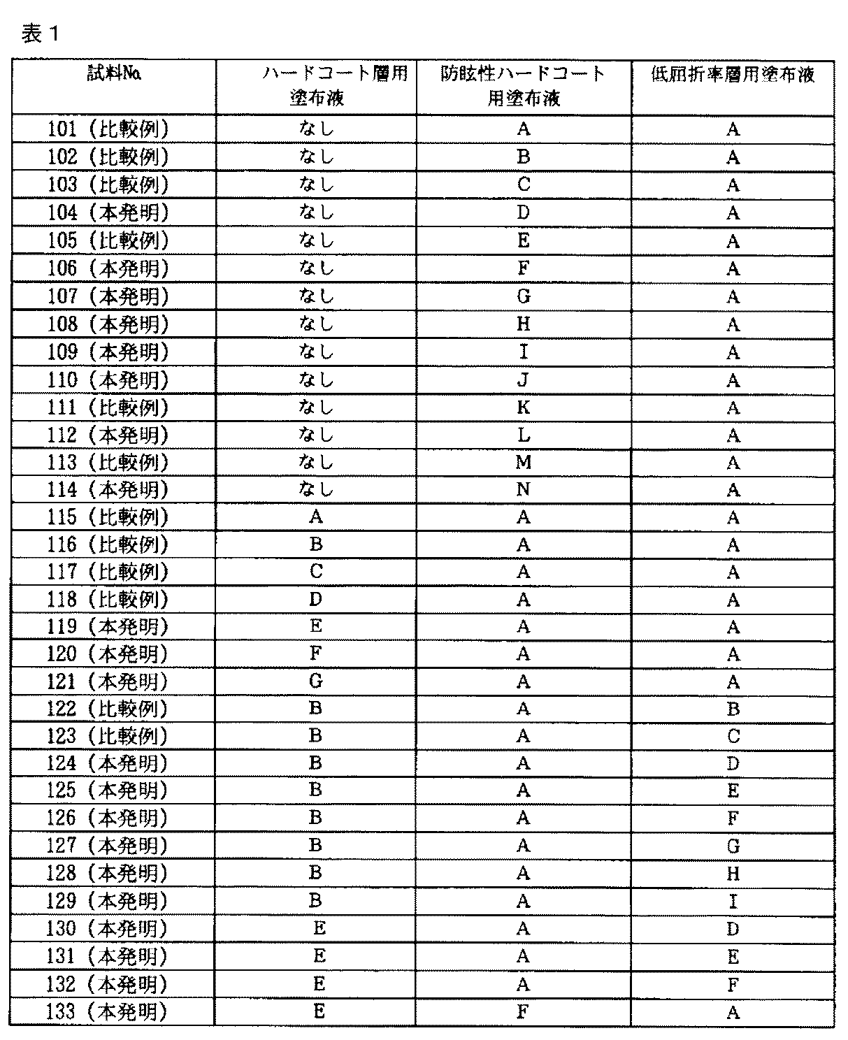
ハードコート層A〜G、防眩性ハードコート層A〜N、低屈折率層A〜Iそれぞれを以下のようにして塗布し、反射防止フィルム試料を得た。積層の組み合わせは表1、表2に記載のとおりに行った。
(1)ハードコート層の塗設
80μmの厚さのトリアセチルセルロースフイルム(TAC−TD80U、商品名、富士写真フイルム(株)製)をロール形態で巻き出して、上記のハードコート層用塗布液を線数180本/インチ、深度40μmのグラビアパターンを有する直径50mmのマイクログラビアロールとドクターブレードを用いて、グラビアロール回転数30rpm、搬送速度10m/分の条件で塗布し、120℃、2分で乾燥の後、酸素濃度0.1%以下の窒素パージ下で160W/cmの空冷メタルハライドランプ(アイグラフィックス(株)製)を用いて、照度400mW/cm2、照射量300mJ/cm2の紫外線を照射して塗布層を硬化させ、厚さ2.5μmのハードコート層を形成し、巻き取った。
【0152】
(2)防眩性ハードコート層の塗設
該ハードコート層を塗設したトリアセチルセルロースフイルムを再び巻き出して、上記の防眩性ハードコート層用塗布液を線数180本/インチ、深度40μmのグラビアパターンを有する直径50mmのマイクログラビアロールとドクターブレードを用いて、グラビアロール回転数30rpm、搬送速度5m/分の条件で塗布し、120℃で4分乾燥の後、窒素パージ下で160W/cmの空冷メタルハライドランプ(アイグラフィックス(株)製)を用いて、照度400mW/cm2、照射量300mJ/cm2の紫外線を照射して塗布層を硬化させ、厚さ2.5μmの防眩性ハードコート層を形成し、巻き取った。
【0153】
(3)低屈折率層の塗設
該ハードコート層と防眩性ハードコート層を塗設したトリアセチルセルロースフイルムを再び巻き出して、上記低屈折率層用塗布液を線数180本/インチ、深度40μmのグラビアパターンを有する直径50mmのマイクログラビアロールとドクターブレードを用いて、グラビアロール回転数30rpm、搬送速度10m/分の条件で塗布し、80℃で2分乾燥の後、さらに窒素パージ下で240W/cmの空冷メタルハライドランプ(アイグラフィックス(株)製)を用いて、照度400mW/cm2、照射量600mJ/cm2の紫外線を照射し、140℃で10分間加熱し、厚さ0.096μmの低屈折率層を形成し、巻き取った。
【0154】
【表1】
【0155】
【表2】
【0156】
上記試料の中から抜粋した試料について防眩性ハードコート層まで塗布した試料について、表面エネルギーと、X線光電子部分光法で測定したフッ素原子由来のピークと炭素原子由来のピーク比F/Cと、シリコン原子由来のピークと炭素原子由来のピーク比Si/Cを以下に示す。なお、防眩性ハードコート層の表面エネルギーは、純水およびジヨードメタンの接触角を測定してOwensの表面エネルギーの式に代入して算出した。
試料116:表面エネルギー 22mN・m−1、 F/C 0.53
試料143:表面エネルギー 31mN・m−1、 F/C 0.28
試料144:表面エネルギー 33mN・m−1、 F/C 0.27
試料145:表面エネルギー 29mN・m−1、 Si/C 0.12
試料146:表面エネルギー 30mN・m−1、 Si/C 0.11
【0157】
(反射防止フィルムの評価)
得られたフィルムについて、以下の項目の評価を行った。
(1)平均反射率
分光光度計(日本分光(株)製)を用いて、380〜780nmの波長領域において、入射角5°における分光反射率を測定した。結果には450〜650nmの積分球平均反射率を用いた。
(2)ヘイズ
得られたフィルムのヘイズをヘイズメーターMODEL 1001DP(商品名、日本電色工業(株)製)を用いて測定した。
(3)鉛筆硬度評価
耐傷性の指標としてJIS K 5400に記載の鉛筆硬度評価を行った。反射防止フィルムを温度25℃、湿度60%RHで2時間調湿した後、JIS S6006に規定する3Hの試験用鉛筆を用いて、1kgの荷重にて
n=5の評価において傷が全く認められない :○
n=5の評価において傷が1または2つ :△
n=5の評価において傷が3つ以上 :×
(4)接触角、指紋付着性評価
表面の耐汚染性の指標として、反射防止フィルムを温度25℃、湿度60%RHで2時間調湿した後、水に対する接触角を測定した。またこのサンプル表面に指紋を付着させてから、それをクリーニングクロスで拭き取ったときの状態を観察して、以下のように指紋付着性を評価した。
指紋が完全に拭き取れる :○
指紋がやや見える :△
指紋がほとんど拭き取れない :×
【0158】
(5)動摩擦係数測定
表面滑り性の指標として動摩擦係数にて評価した。動摩擦係数は試料を25℃、相対湿度60%で2時間調湿した後、HEIDON−14(商品名)動摩擦測定機により5mmステンレス鋼球、荷重100g、速度60cm/minにて測定した値を用いた。
(6)防眩性評価
作成した防眩性フィルムにルーバーなしのむき出し蛍光灯(8000cd/m2)を映し、その反射像のボケの程度を以下の基準で評価した。
蛍光灯の輪郭が全くわからない :◎
蛍光灯の輪郭がわずかにわかる :○
蛍光灯はぼけているが、輪郭は識別できる :△
蛍光灯がほとんどぼけない :×
(7)ギラツキ評価
作成した防眩性フィルムにルーバーありの蛍光灯拡散光を映し、表面のギラツキを以下の基準で評価した。
ほとんどギラツキが見られない :○
わずかにギラツキがある :△
目で識別できるサイズのギラツキがある :×
【0159】
(8)スチールウール耐傷性評価
ラビングテスターを用いて、以下の条件でこすりテストをおこなった。
試料調湿条件: 25℃、60%RH、2時間以上。
こすり材: 試料と接触するテスターのこすり先端部(1cm×1cm)にスチールウール(日本スチールウール製、ゲレードNo.0000)を巻いて、動かないようバンド固定した。
移動距離(片道):13cm、 こすり速度:13cm/秒、 荷重:200g/cm2、 先端部接触面積:1cm×1cm、 こすり回数:20往復。
こすり終えた試料の裏側に油性黒インキを塗り、反射光で目視観察して、こすり部分の傷を、以下の基準で評価した。
非常に注意深く見ても、全く傷が見えない。 : ◎
非常に注意深く見ると僅かに弱い傷が見える。 : ○
弱い傷が見える。 : ○△
中程度の傷が見える。 : △
一目見ただけで強い傷が見える。 : ×
【0160】
(9)水綿棒こすり耐性評価
ラビングテスターのこすり先端部に綿棒を固定し、平滑皿中で試料の上下をクリップで固定し、室温25℃で、試料と綿棒を25℃の水に浸し、綿棒に500gの荷重をかけて、こすり回数を変えてこすりテストを行った。こすり条件は以下のとおり。
こすり距離(片道):1cm、 こすり速度:約2往復/秒
こすり終えた試料を観察して、膜剥がれが起こった回数で、こすり耐性を以下のように評価した。
0〜10往復で膜剥がれ ×
10〜30往復で膜剥がれ ×△
30〜50往復で膜剥がれ △
50〜100往復で膜剥がれ ○△
100〜150往復で膜剥がれ ○
150往復でも膜剥がれなし ◎
【0161】
(10)塗布面状ムラ
塗布面側を上にして、裏面側から上記蛍光灯を照射して、透過目視面検にてハジキ、ブツ等の点欠陥、塗布ムラ、乾燥ムラ等の面状ムラの発生頻度について、10m2だけ検査し、その値を10で割って1m2当たりの面状ムラの数を算出した。
【0162】
上記試料中の本発明の試料において、指紋付着性は○で、防眩性は◎で、ギラツキは○であり、反射防止性能と鉛筆硬度も防眩性反射防止フィルムに必要とされる性能レベルを越えていた。
また試料116、143〜146について面状ムラの数を数えた。
試料116 9個/m2
試料143 3個/m2
試料144 0個/m2
試料145 3個/m2
試料146 1個/m2
その結果、防眩性ハードコート層にフッ素系界面活性剤を含有することにより塗布面状ムラ低減効果が確認された。
その他の評価結果について表3,4に示す。
本発明の試料104、106〜110、112、114、119〜121、124〜142、144、146〜149、151、152は、比較例試料101〜103、105、111、113、115〜118、122、123、143、145、150に比べて、スチールウール耐傷性と綿棒こすり性能が優れていることが分かる。特に、防眩性ハードコート層と低屈折率層の両層に本発明の化合物を含有した系が耐傷性能に優れることが分かる。これらの効果は本発明のシラン系化合物の含有によることが明らかである。
【0163】
【表3】
【0164】
【表4】
【0165】
次に、本発明の試料104、106〜110、112、114、119〜121、124〜142、144、146〜149、151、152のフィルムを偏光板における偏光層の保護フィルムとして用いて防眩性反射防止偏光板を作成した。この偏光板を用いて反射防止フィルムの低屈折率層が最表層になるように配置した液晶表示装置を作製したところ、外光の映り込みがないために優れたコントラストが得られ、防眩性により反射像が目立たず優れた視認性を有していた。さらに同様にして、上記本発明の試料を偏光子、透明支持体およびディスコティック液晶の配向を固定した光学異方層から構成される光学補償フィルム、並びに光散乱層からなる偏光板と組み合わせて液晶表示装置を作製して視認性を評価したところ、外光の映り込みがなく、優れたコントラストが得られ、防眩性により反射像が目立たず優れた性能を有していた。
【0166】
(反射防止フィルムの鹸化処理)
前記試料101〜152について、以下の処理を行った。
1.5Nの水酸化ナトリウム水溶液を調製し、50℃に保温した。0.01Nの希硫酸水溶液を調製した。
作製した反射防止フィルムを上記の水酸化ナトリウム水溶液に2分間浸漬した後、水に浸漬し水酸化ナトリウム水溶液を十分に洗い流した。次いで、上記の希硫酸水溶液に1分間浸漬した後、水に浸漬し希硫酸水溶液を十分に洗い流した。さらに反射防止フィルムを100℃で十分に乾燥させた。
このようにして、鹸化処理済み反射防止フィルムを作製した。
【0167】
(11)鹸化処理による膜の剥がれの評価
鹸化処理過程での膜の剥がれ評価した。100枚の反射防止フィルムを鹸化処理した。鹸化処理前と鹸化処理後における膜の剥がれの有無を目視で観察し、下記の3段階評価を行った。
〇:100枚全てにおいて剥がれが全く認められなかったもの
△:剥がれが認められたものが5枚以内のもの
×:剥がれが認められたものが5枚をこえたもの
(12)碁盤目密着の評価
偏光板用保護フィルム(反射防止フィルム)を温度25℃、相対湿度60%の条件で2時間調湿した。偏光板用保護フィルムの最外層を有する側の表面において、カッターナイフで碁盤目状に縦11本、横11本の切り込みを入れ、日東電工(株)製のポリエステル粘着テープ(NO.31B)における密着試験を同じ場所で繰り返し3回行った。膜の剥がれの有無を目視で観察し、下記の3段階評価を行った。
〇:100枡において剥がれが全く認められなかったもの
△:剥がれが認められたものが2枡以内のもの
×:剥がれが認められたものが2枡をこえたもの
【0168】
鹸化処理を行った、剥がれ、密着評価結果について記す。
本発明のいずれの試料においても、鹸化処理による膜の剥がれの評価は○であり、および碁盤目密着の評価も○でありいずれの評価試験も膜の剥がれは、観察されなかった。
また、本発明の試料について、防眩性ハードコート層および低屈折率層とは支持体を挟んだ反対側面の水に対する接触角を測定したところ、いずれの試料においても40°から30°の範囲に入っていた。
【0169】
[実施例2]
防眩性ハードコート層用塗布液イ〜ニ、低屈折率層用塗布液A〜Iを実施例1と同様にして塗布した。積層の組み合わせは表5に記載のとおりにおこなった。
【0170】
【表5】
【0171】
(反射防止膜の評価)
得られた試料201〜228について、実施例1と同様の評価を行った。
本発明の試料202〜228について、いずれの試料においても、指紋付着性は○で、防眩性は○で、ギラツキは◎であり、反射防止性能と鉛筆硬度も防眩性反射防止フィルムに必要とされる性能レベルを越えていた。
その他の評価結果について表6に示す。
本発明の試料202〜228は、比較例試料201に比べて、実施例1と同様に、スチールウール耐傷性と綿棒こすり性能が優れていることが分かる。特に、防眩性ハードコート層と低屈折率層の両層に本発明の化合物を含有した系が耐傷性能に優れることが分かる。これらの効果は本発明のシラン系化合物の含有によることが明らかである。
【0172】
【表6】
【0173】
次に、実施例1と同様にして、本発明の試料202〜228のフィルムを用いて防眩性反射防止偏光板を作成した。この偏光板を用いて反射防止フィルムの低屈折率層が最表層になるように配置した液晶表示装置を作成したところ、外光の映り込みがないために優れたコントラストが得られ、防眩性により反射像が目立たず優れた視認性を有していた。
さらに同様にして、上記本発明の試料を偏光子の片側に貼合し、反対側に透明支持体およびディスコティック液晶の配向を固定した光学異方層から構成される光学補償フィルムを貼合した楕円偏光板を用いて液晶表示装置を作製して視認性を評価したところ、外光の映り込みがなく、優れたコントラストが得られ、防眩性により反射像が目立たず優れた性能を有していた。
【0174】
(反射防止フィルムの鹸化処理)
前記試料202〜228について、実施例1と同様の鹸化処理を行った。
鹸化処理を行った試料201〜228について、実施例1と同様の鹸化処理による膜の剥がれ、碁盤目密着の評価を行った。
その結果、いずれの試料においても、鹸化処理による膜の剥がれ、および碁盤目密着の剥がれは、観察されなかった。
また、本発明の試料202〜228について、防眩性ハードコート層および低屈折率層とは支持体を挟んだ反対側面の水に対する接触角を測定したところ、いずれの試料においても40°から30°の範囲に入っていた。
【0175】
[実施例3]
PVAフィルムをヨウ素2.0g/l、ヨウ化カリウム4.0g/lの水溶液に25℃にて240秒浸漬し、さらにホウ酸10g/lの水溶液に25℃にて60秒浸漬後、図2の形態のテンター延伸機に(イ)から導入し、5.3倍に延伸し、テンターを延伸方向に対し図2の如く屈曲させ、以降幅を一定に保った。80℃雰囲気で乾燥させた後テンターから離脱した。左右のテンタークリップの搬送速度差は、0.05%未満であり、導入されるフィルムの中心線21と次工程に送られるフィルムの中心線22のなす角は、46゜であった。ここで|L1−L2|は0.7m、Wは0.7mであり、|L1−L2|=Wの関係にあった。テンター出口における実質延伸方向Ax−Cxは、次工程へ送られるフィルムの中心線22に対し45゜傾斜していた。テンター出口におけるシワ、フィルム変形は観察されなかった。
さらに、PVA((株)クラレ製PVA−117H(商品名))3%水溶液を接着剤としてケン化処理した富士写真フィルム(株)製フジタック(商品名、セルローストリアセテート、レターデーション値3.0nm)と貼り合わせ、さらに80℃で乾燥して有効幅650mmの偏光板を得た。得られた偏光板の吸収軸方向は、長手方向に対し45゜傾斜していた。この偏光板の550nmにおける透過率は43.7%、偏光度は99.97%であった。さらに図2の如く310×233mmサイズに裁断したところ、91.5%の面積効率で辺に対し45゜吸収軸が傾斜した偏光板を得た。図3中、81は吸収軸(延伸軸)を82は長手方向を示す。
次に、実施例1の本発明の試料104、106〜110、112、114、119〜121、124〜142、144、146〜149、151、152の鹸化処理したフィルムを上記偏光板と貼り合わせて防眩性反射防止フィルム付き偏光板を作製した。この偏光板を用いて反射防止フィルムの低屈折率層が最表層になるように配置した液晶表示装置を作製したところ、外光の映り込みがないために優れたコントラストが得られ、防眩性により反射像が目立たず優れた視認性を有していた。
【0176】
[実施例4]
上記実施例3の45°吸収軸が傾斜した偏光板作製の中の、「富士写真フイルム(株)製フジタック(セルローストリアセテート、レターデーション値3.0nm)」の代わりに実施例1の本発明の試料104、106〜110、112、114、119〜121、124〜142、144、146〜149、151、152の鹸化処理したフィルムを張り合わせて防眩性反射防止フィルム付き偏光板を作製した。この偏光板を用いて反射防止フィルムの低屈折率層が最表層になるように配置した液晶表示装置を作製したところ、実施例3同様に、外光の映り込みがないために優れたコントラストが得られ、防眩性により反射像が目立たず優れた視認性を有していた。
【0177】
[実施例5]
実施例1で作製した本発明の試料104、106〜110、112、114、119〜121、124〜142、144、146〜149、151、152を、1.5規定、55℃のNaOH水溶液中に2分間浸漬したあと中和、水洗してフィルムの裏面のトリアセチルセルロース面を鹸化処理し、80μmの厚さのトリアセチルセルロースフイルム(TAC−TD80U、富士写真フイルム(株)製)を同条件で鹸化処理したフィルムにポリビニルアルコールにヨウ素を吸着させ、延伸して作製した偏光子の両面を接着、保護して偏光板を作製した。このようにして作製した偏光板を、反射防止フィルムの低屈折率層側が最表面となるように透過型TN液晶表示装置搭載のノートパソコンの液晶表示装置(偏光選択層を有する偏光分離フィルムである住友3M(株)製のD−BEF(商品名)をバックライトと液晶セルとの間に有する)の視認側の偏光板と貼り代えたところ、背景の映りこみが極めて少なく、表示品位の非常に高い表示装置が得られた。
【0178】
[実施例6]
実施例1で作製した本発明の試料104、106〜110、112、114、119〜121、124〜142、144、146〜149、151、152を、低屈折率層が最表層になるように貼りつけた透過型TN液晶セルの視認側の偏光板の液晶セル側の保護フィルム、およびバックライト側の偏光板の液晶セル側の保護フィルムに、ディスコティック構造単位の円盤面が透明支持体面に対して傾いており、且つ該ディスコティック構造単位の円盤面と透明支持体面とのなす角度が、光学異方層の深さ方向において変化している光学補償層を有する視野角拡大フィルム(ワイドビューフィルムSA−12B、商品名、富士写真フイルム(株)製)を用いたところ、明室でのコントラストに優れ、且つ、上下左右の視野角が非常に広く、極めて視認性に優れ、表示品位の高い液晶表示装置が得られた。
【0179】
[実施例7]
実施例1で作製した本発明の試料104、106〜110、112、114、119〜121、124〜142、144、146〜149、151、152を、低屈折率層が最表層になるように有機EL表示装置の表面のガラス板に粘着剤を介して貼り合わせたところ、ガラス表面での反射が抑えられ、視認性の高い表示装置が得られた。
【0180】
[実施例8]
実施例1で作製した本発明の試料104、106〜110、112、114、119〜121、124〜142、144、146〜149、151、152を用いて、低屈折率層が最表層になるように片面反射防止フィルム付き偏光板を作製した。この偏光板の反射防止フィルムを有している側の反対面にλ/4板を張り合わせて、得られた偏光板を低屈折率層が最表層になるように有機EL表示装置の表面のガラス板に貼り付けたところ、表面反射および、表面ガラスの内部からの反射がカットされ、極めて視認性の高い表示が得られた。
【0181】
【発明の効果】
本発明の反射防止フィルムは、十分な反射防止性能と防汚性を有し、かつ、耐傷性に優れる。また、本発明の反射防止フィルムの製造方法によれば、上記反射防止フィルムを高い生産性で安定して得ることができる。
さらに、このような反射防止フィルムを用いた本発明の偏光板およびディスプレイ装置は十分な反射防止性能を有し視認性に優れる。
【図面の簡単な説明】
【図1】防眩性反射防止フィルムの層構成を示す断面模式図である。
【図2】実施例3で使用のテンター延伸機を示す概略図である。
【図3】実施例3の偏光板の裁断方法を示す説明図である。
【符号の説明】
1 防眩性反射防止フィルム
2 透明支持体
3 ハードコート層
4 防眩性ハードコート層
5 低屈折率層
6 マット粒子
(イ) フィルム導入方向
(ロ) 次工程へのフィルム搬送方向
(a) フィルムを導入する工程
(b) フィルムを延伸する工程
(c) 延伸フィルムを次工程へ送る工程
A1 フィルムの保持手段への噛み込み位置とフィルム延伸の起点位置(実質保持開始点:右)
B1 フィルムの保持手段への噛み込み位置(左)
C1 フィルム延伸の起点位置(実質保持開始点:左)
Cx フィルム離脱位置とフィルム延伸の終点基準位置(実質保持解除点:左)
Ay フィルム延伸の終点基準位置(実質保持解除点:右)
|L1−L2| 左右のフィルム保持手段の行程差
W フィルムの延伸工程終端における実質幅
δ 延伸方向とフィルム進行方向のなす角
21 導入側フィルムの中央線
22 次工程に送られるフィルムの中央線
23 フィルム保持手段の軌跡(左)
24 フィルム保持手段の軌跡(右)
25 導入側フィルム
26 次工程に送られるフィルム
27a、27b 左右のフィルム保持開始(噛み込み)点
28a、28b 左右のフィルム保持手段からの離脱点[0001]
BACKGROUND OF THE INVENTION
The present invention relates to an antireflection film, a polarizing plate, and a display device using the same.
[0002]
[Prior art]
Anti-reflection films are generally used in display devices such as cathode ray tube display (CRT), plasma display (PDP), electroluminescence display (ELD), and liquid crystal display (LCD) to reduce contrast and reflect images. In order to prevent engraving, it is placed on the outermost surface of the display to reduce reflectivity using the principle of optical interference.
[0003]
Such an antireflection film can be produced by forming a high refractive index layer on a support and a low refractive index layer having an appropriate film thickness thereon. In order to realize a low reflectance, a material having a refractive index as low as possible is desired for the low refractive index layer. Further, since the antireflection film is used on the outermost surface of the display, high scratch resistance is required. In order to realize high scratch resistance in a thin film having a thickness of around 100 nm, the strength of the coating itself and the adhesion to the lower layer are required.
[0004]
In order to lower the refractive index of the material, there are means of (1) introducing fluorine atoms and (2) lowering the density (introducing voids), but in any case, the film strength and adhesion are impaired and the scratch resistance is lowered. Therefore, it was difficult to achieve both a low refractive index and high scratch resistance.
[0005]
JP-A-11-189621, JP-A-11-228631, and JP-A-2000-313709 disclose means for reducing the coefficient of friction of the coating surface and improving the scratch resistance by introducing a polysiloxane structure into the fluoropolymer. Has been described. This means is effective to some extent for improving scratch resistance, but sufficient scratch resistance cannot be obtained only by this method for a film having an essential film strength and interfacial adhesion.
[0006]
On the other hand, Japanese Patent Application No. 2002-23808 describes that scratch resistance is greatly improved by adding a silane coupling agent to a low refractive index layer material using a fluorine-containing polymer. However, the silane coupling agent having a low boiling point has a problem that it volatilizes in the coating and drying process, and requires an excessive amount of addition considering the volatilized content, and there is a problem that it is difficult to obtain stable performance.
[0007]
The present inventors can obtain stable performance even with a small addition amount by using a polymer obtained by vinyl-polymerizing a silane coupling agent having a polymerization group in advance, and when the silane coupling agent is added as it is. It has been found that a greater effect can be obtained.
[0008]
[Problems to be solved by the invention]
An object of the present invention is to provide an antireflection film having improved anti-scratch properties while having sufficient antireflection performance and antifouling properties.
Furthermore, it is providing the manufacturing method which can obtain such an antireflection film with high productivity.
Furthermore, it is providing the polarizing plate and display apparatus using such an antireflection film.
[0009]
[Means for Solving the Problems]
According to the present invention, an antireflection film, a polarizing plate and a display device having the following constitution are provided, and the above object is achieved.
(1) An optical film having at least a hard coat layer and a low refractive index layer containing a fluorine-containing polymer on a transparent support, wherein at least one of the hard coat layer to the low refractive index layer has the following general formula ( An antireflective film comprising a vinyl polymer containing a constituent component from the compound represented by 1).
General formula (1)
[0010]
[Chemical 2]
(Wherein R1Represents a hydrogen atom, a methyl group, a methoxy group, an alkoxycarbonyl group, a cyano group, a fluorine atom or a chlorine atom. Y represents a single bond or an ester group, an amide group, an ether group or a urea group. L represents a divalent linking chain. X1, X2, X3Each independently represents a halogen atom, a hydroxyl group, an alkoxy group, or a substituted or unsubstituted acyloxy group. )
(2) The antireflection film as described in (1), wherein at least one of the hard coat layers is an antiglare hard coat layer.
(3) The antireflection film as described in (2), further comprising a hard coat layer having no antiglare property in a lower layer of the antiglare hard coat layer.
(4) The antiglare hard coat layer is formed of a binder and matte particles having an average particle diameter of 1.0 to 10.0 μm, and the refractive index of the binder is 1.48 to 2.00. The antireflection film according to any one of (2) to (3).
[0012]
(5) The hard coat layer contains an inorganic filler composed of at least one oxide selected from zirconium, titanium, aluminum, indium, zinc, tin, antimony, and silicon (1) to The antireflection film as described in (4).
(6) The antireflection film as described in (1) to (5), wherein the low refractive index layer contains an inorganic filler selected from silica and magnesium fluoride.
(7) The hard coat layer having no antiglare property below the antiglare hard coat layer contains an inorganic filler selected from silica and alumina, as described in (3) to (6) Antireflection film.
(8) The antireflection film as described in any one of (1) to (7), wherein all hard coat layers and low refractive index layers contain inorganic filler particles.
[0013]
(9) The antireflection film as described in (5) to (8), wherein the inorganic filler has an average particle size of 0.001 to 0.2 μm.
(10) In (1) to (9), the dynamic friction coefficient of the surface on the low refractive index layer side is 0.03 to 0.15, and the contact angle with water is 90 to 120 °. The antireflection film as described.
(11) The surface energy of the hard coat layer is 25 mN · m-1~ 70mN ・ m-1The antireflection film according to any one of (1) to (10), wherein
(12) The antireflection film as described in any one of (2) to (11), wherein the antiglare hard coat layer contains a fluorine-based and / or silicone-based surfactant.
[0014]
(13) The antiglare hard coat layer has a ratio of a peak derived from a fluorine atom and a peak derived from a carbon atom measured by X-ray photoelectron spectroscopy, and F / C is 0.40 or less, and / or derived from a silicon atom The antireflection film as described in any one of (2) to (12), wherein Si / C, which is the ratio of the peak to the peak derived from carbon atoms, is 0.30 or less.
(14) The antireflection film as described in (1) to (13), wherein the haze is 3.0 to 50.0%, and the average reflectance at 450 to 650 nm is 2.2% or less.
(15) The antireflection film as described in (1) to (14), wherein the transparent support is triacetyl cellulose, polyethylene terephthalate, or polyethylene naphthalate.
(16) The antireflection film as described in any one of (1) to (15), wherein the surface of the transparent support opposite to the side having the low refractive index layer has a contact angle with water of 40 ° or less.
[0015]
(17) The antireflection film as described in any one of (1) to (16), wherein the vinyl polymer does not contain a fluorine atom.
(18) The antireflection film as described in any one of (1) to (17), wherein the fluoropolymer is a perfluoroolefin copolymer.
(19) The antireflection film as described in any one of (1) to (18), wherein the fluorine-containing polymer is a polymer having a repeating unit having a radical polymerizable group or a cationic ring-opening polymerizable group in the side chain.
[0016]
(20) A low refractive index layer containing at least a hard coat layer and a fluorine-containing polymer is coated on the transparent support. In producing the antireflection film as described in (1) to (19), the hard coat layer A method for producing an antireflection film, wherein the coating liquid for at least one layer for use or a low refractive index layer contains a vinyl polymer containing a constituent component from the compound represented by the general formula (1).
(21) The method for producing an antireflection film as described in (20), which is obtained by forming a low refractive index layer on a transparent support, followed by saponification treatment.
[0017]
(22) The low refractive index layer is formed by a coating step, the solvent of the coating solution for the low refractive index layer is composed of at least one solvent, and 50 to 100% by mass of the solvent is composed of a solvent having a boiling point of 100 ° C. or less. (20) The manufacturing method of the antireflection film as described in (21) characterized by the above-mentioned.
(23) The method for producing an antireflection film as described in any one of (20) to (22), wherein the solvent of the coating solution for the low refractive index layer is a ketone and / or an ester.
(24) A roll-shaped transparent support is continuously unwound, and at least one of a hard coating layer or a low refractive index layer containing a fluorine-containing polymer is microgravureed on one side of the unwound support. The method for producing an antireflection film according to any one of (20) to (23), wherein coating is performed by a coating method.
(25) The antireflection film according to (1) to (19) or the antireflection film produced by the production method according to (20) to (24) A polarizing plate characterized by being used for at least one of them.
(26) An antireflection film according to (1) to (19), an antireflection film produced by the production method according to (20) to (24), or a display device having the polarizing plate according to (25). The display device is characterized in that the low refractive index layer is disposed on the viewing side.
[0018]
DETAILED DESCRIPTION OF THE INVENTION
A basic configuration of an antireflection film suitable as an embodiment of the present invention will be described with reference to the drawings.
[0019]
1 is a cross-sectional view showing an example of the antireflection film of the present invention. In this case, the antireflection film 1 includes a transparent support 2, a hard coat layer 3, and an antiglare hard coat layer. 4 and a low refractive index layer 5 having the lowest refractive index. Fine particles 6 are dispersed in the antiglare hard coat layer 4, and the refractive index of the material other than the fine particles 6 of the antiglare hard coat layer 4 is in the range of 1.57 to 2.00. The refractive index of the low refractive index layer 5 is preferably in the range of 1.38 to 1.49. In the present invention, the hard coat layer may be a hard coat layer having an antiglare property as described above, a hard coat layer having no antiglare property, or a single layer, or a plurality of layers, for example, 2 to 4 layers. It may be comprised. Therefore, the hard coat layer 3 shown in FIG. 1 is not essential, but is preferably applied for imparting film strength. Similarly, the low refractive index layer may be composed of one layer or a plurality of layers.
[0020]
At least one of the hard coat layer and the low refractive index layer of the present invention contains a vinyl polymer containing a constituent component from a vinyl monomer represented by the following general formula (1).
General formula (1)
[0021]
[Chemical 3]
[0022]
The vinyl monomer represented by the general formula (1) will be described.
In the general formula (1), R1Represents a hydrogen atom, a methyl group, a methoxy group, an alkoxycarbonyl group, a cyano group, a fluorine atom or a chlorine atom. Examples of the alkoxycarbonyl group include a methoxycarbonyl group and an ethoxycarbonyl group. A hydrogen atom, methyl group, methoxy group, methoxycarbonyl group, cyano group, fluorine atom or chlorine atom is preferred, a hydrogen atom, methyl group, methoxycarbonyl group, fluorine atom or chlorine atom is more preferred, and a hydrogen atom or methyl group is particularly preferred preferable.
Y represents a single bond or an ester group, an amide group, an ether group or a urea group. A single bond or an ester group or an amide group is preferred, a single bond or an ester group is more preferred, and an ester group is particularly preferred.
[0023]
L represents a divalent linking chain. Specifically, it has a substituted or unsubstituted alkylene group, a substituted or unsubstituted arylene group, a substituted or unsubstituted alkylene group having a linking group (for example, ether, ester, amide) inside, and a linking group inside. Examples thereof include substituted or unsubstituted arylene groups, substituted or unsubstituted alkylene groups having 2 to 10 carbon atoms, substituted or unsubstituted arylene groups having 6 to 20 carbon atoms, and 3 to 10 carbon atoms having a linking group therein. An alkylene group is preferably an unsubstituted alkylene group, an unsubstituted arylene group, an alkylene group having an ether or ester linking group therein, an unsubstituted alkylene group, and an ether or ester linking group inside. An alkylene group having
[0024]
X1, X2, X3Each independently represents a halogen atom, a hydroxyl group, a substituted or unsubstituted alkoxy group, or a substituted or unsubstituted acyloxy group. A halogen atom, a hydroxyl group and an unsubstituted alkoxy group are preferable, a chlorine, a hydroxyl group and an unsubstituted alkoxy group having 1 to 6 carbon atoms are more preferable, a hydroxyl group and an alkoxy group having 1 to 3 carbon atoms are more preferable, and a methoxy group is particularly preferable. preferable.
[0025]
Although there is no restriction | limiting in particular as a substituent, A halogen atom (fluorine, chlorine, bromine, etc.), a hydroxyl group, a mercapto group, a carboxyl group, an epoxy group, an alkyl group (methyl, ethyl, i-propyl, propyl, t-butyl etc.) , Aryl groups (phenyl, naphthyl, etc.), aromatic heterocyclic groups (furyl, pyrazolyl, pyridyl, etc.), alkoxy groups (methoxy, ethoxy, i-propoxy, hexyloxy, etc.), aryloxy (phenoxy, etc.), alkylthio groups ( Methylthio, ethylthio, etc.), arylthio groups (phenylthio, etc.), alkenyl groups (vinyl, 1-propenyl, etc.), acyloxy groups (acetoxy, acryloyloxy, methacryloyloxy, etc.), alkoxycarbonyl groups (methoxycarbonyl, ethoxycarbonyl, etc.), aryl Oxycarbonyl group Phenoxycarbonyl, etc.), carbamoyl groups (carbamoyl, N-methylcarbamoyl, N, N-dimethylcarbamoyl, N-methyl-N-octylcarbamoyl, etc.), acylamino groups (acetylamino, benzoylamino, acrylicamino, methacrylamino, etc.), etc. These substituents may be further substituted.
Among these, a halogen, an alkyl group, an alkoxy group, an alkoxyalkyl group, an acyloxy group, and an acylamino group are preferable, an alkyl group, an alkoxy group, and an alkoxyalkyl group are more preferable, and an alkyl group and an alkoxy group are particularly preferable.
Specific examples of the compound represented by the general formula (1) are shown below, but the present invention is not limited thereto.
[0026]
[Formula 4]
[0027]
[Chemical formula 5]
[0028]
[Chemical 6]
[0029]
The vinyl polymer may be composed only of the structural component from the general formula (1) or may be a copolymer with a vinyl monomer other than the general formula (1) (hereinafter referred to as other vinyl monomer).
Examples of other vinyl monomers include the following. That is, acrylic acid or methacrylic acid, acrylic acid esters or methacrylic acid esters (the ester group is an alkyl group or aryl group which may have a substituent, such as a methyl group, an ethyl group, an n-propyl group, Isopropyl group, n-butyl group, sec-butyl group, tert-butyl group, hexyl group, 2-ethylhexyl group, tert-octyl group, 2-chloroethyl group, cyanoethyl group, 2-acetoxyethyl group, tetrahydrofurfuryl group, 5-hydroxypentyl group, cyclohexyl group, benzyl group, hydroxyethyl group, 3-methoxybutyl group, 2- (2-methoxyethoxy) ethyl group, 2,2,2-tetrafluoroethyl group, 1H, 1H, 2H, 2H-perfluorodecyl group, phenyl group, 2,4,5-tetramethylphenyl group, 4-c Rofeniru group).
[0030]
Vinyl esters, specifically, aliphatic carboxylic acid vinyl esters which may have a substituent (for example, vinyl acetate, vinyl propionate, vinyl butyrate, vinyl isobutyrate, vinyl caproate, vinyl chloro) Acetate), aromatic carboxylic acid vinyl esters which may have a substituent (for example, vinyl benzoate, vinyl 4-methylbenzoate, vinyl salicylate, etc.).
[0031]
Acrylamides, specifically, acrylamide, N-monosubstituted acrylamide, N-disubstituted acrylamide (the substituent is an alkyl group, an aryl group, or a silyl group which may have a substituent, such as a methyl group, n -Propyl group, isopropyl group, n-butyl group, tert-butyl group, tert-octyl group, cyclohexyl group, benzyl group, hydroxymethyl group, alkoxymethyl group, phenyl group, 2,4,5-tetramethylphenyl group, 4-chlorophenyl group, trimethylsilyl, etc.).
[0032]
Methacrylamide, specifically, methacrylamide, N-monosubstituted methacrylamide, N-disubstituted methacrylamide (substituent is an alkyl group, aryl group, silyl group which may have a substituent, for example, Methyl group, n-propyl group, isopropyl group, n-butyl group, tert-butyl group, tert-octyl group, cyclohexyl group, benzyl group, hydroxymethyl group, alkoxymethyl group, phenyl group, 2,4,5-tetra Methylphenyl group, 4-chlorophenyl group, trimethylsilyl, etc.).
[0033]
Olefins (eg, ethylene, propylene, 1-pentene, vinyl chloride, vinylidene chloride, isoprene, chloroprene, butadiene, etc.), styrenes (eg, styrene, methyl styrene, isopropyl styrene, methoxy styrene, acetoxy styrene, chlorostyrene, etc.) Vinyl ethers (for example, methyl vinyl ether, butyl vinyl ether, hexyl vinyl ether, methoxyethyl vinyl ether, etc.).
[0034]
Other monomers include crotonic acid ester, itaconic acid ester, maleic acid diester, fumaric acid diester, methyl vinyl ketone, phenyl vinyl ketone, methoxyethyl vinyl ketone, N-vinyl oxazolidone, N-vinyl pyrrolidone, vinylidene chloride, methylene malon nitrile Vinylidene, diphenyl-2-acryloyloxyethyl phosphate, diphenyl-2-methacryloyloxyethyl phosphate, dibutyl-2-acryloyloxyethyl phosphate, dioctyl-2-methacryloyloxyethyl phosphate, and the like.
[0035]
20-100 mass% is preferable, the ratio for which the structural component from the vinyl monomer of the said General formula (1) in the said vinyl polymer accounts is more preferable, 40-100 mass% is more preferable, 60-100 mass% is more preferable, 80 ˜100 mass% is particularly preferred.
[0036]
Specific examples of the vinyl polymer are shown below, but the present invention is not limited thereto. The ratio in parentheses means the mass ratio. The present invention is not limited to these specific examples.
[0037]
P-1) M-1 homopolymer
P-2) M-2 homopolymer
P-3) M-1 / n-butyl methacrylate copolymer (80:20)
P-4) M-1 / 2-hydroxyethyl acrylate copolymer (70:30)
P-5) M-1 / glycidyl acrylate copolymer (90:10)
P-6) M-1 / N, N-dimethylacrylamide copolymer (90:10)
P-7) M-2 / styrene copolymer (70:30)
P-8) M-2 / ethyl methacrylate copolymer (70:30)
P-9) M-2 / N-vinylpyrrolidone copolymer (75:25)
P-10) M-2 / methacrylamide copolymer (95: 5)
P-11) M-1 / M-2 copolymer (70:30)
P-12) M-1 / M-2 / 2-ethylhexyl acrylate copolymer (60:30:10)
P-13) M-13 homopolymer
P-14) M-15 homopolymer
P-15) M-18 homopolymer
P-16) M-3 homopolymer
P-17) M-1 / 2-carboxyethyl acrylate copolymer (80:20)
P-18) M-1 / acrylonitrile copolymer (80:20)
P-19) M-2 / M-3 copolymer (80:20)
P-20) M-4 / ethyl acrylate / dioctyl-2-methacryloyloxyethyl phosphate copolymer (70:20:10)
[0038]
The molecular weight (Mw) of the vinyl polymer is usually 1000 to 200000, preferably 2000 to 50000. When the molecular weight is less than 1000, the effect of the present invention tends to be difficult to obtain. When the molecular weight is greater than 200000, the solubility in an organic solvent is deteriorated, or the viscosity of the organic solvent solution is increased, resulting in restrictions on formulation design. Tend to occur.
[0039]
The appropriate content of the vinyl polymer is small in the case of a surface layer that is a relatively thin film, and is often necessary in the case of a lower layer that is a thick film. 50 mass% is preferable, 0.5-20 mass% is more preferable, 1-10 mass% is the most preferable.
[0040]
The antireflection film of the present invention has a hard coat layer on a transparent support, and further has a low refractive index layer thereon. Depending on the required performance, one layer of the hard coat is antiglare hard coat layer. The antireflection film can be obtained.
In the antireflection film of the present invention, a hard coat layer that is not anti-glare can be further provided under the anti-glare hard coat layer for the purpose of improving the film strength.
[0041]
Furthermore, it is preferable to add an inorganic filler to each layer on the support. The inorganic filler added to each layer may be the same or different, and the type and amount added are preferably adjusted according to the required performance such as the refractive index, film strength, film thickness, and coating property of each layer.
The shape of the inorganic filler used in the present invention is not particularly limited, and for example, any of a spherical shape, a plate shape, a fiber shape, a rod shape, an indeterminate shape, a hollow shape, and the like are preferably used. . Further, the kind of the inorganic filler is not particularly limited, but an amorphous one is preferably used, and is preferably made of a metal oxide, nitride, sulfide or halide. Particularly preferred. As metal atoms, Na, K, Mg, Ca, Ba, Al, Zn, Fe, Cu, Ti, Sn, In, W, Y, Sb, Mn, Ga, V, Nb, Ta, Ag, Si, B Bi, Mo, Ce, Cd, Be, Pb, Ni and the like. In order to obtain a transparent cured film, the average particle diameter of the inorganic filler is preferably set to a value within the range of 0.001 to 0.2 μm, more preferably 0.001 to 0.1 μm, and still more preferably. 0.001 to 0.06 μm. Here, the average particle diameter of the particles is measured by a Coulter counter.
Although the usage method of the inorganic filler in this invention is not restrict | limited in particular, For example, it can use in a dry state or can also be used in the state disperse | distributed to water or the organic solvent.
In the present invention, it is also preferable to use a dispersion stabilizer in combination for the purpose of suppressing aggregation and sedimentation of the inorganic filler. Dispersion stabilizers include polyvinyl alcohol, polyvinyl pyrrolidone, cellulose derivatives, polyamides, phosphate esters, polyethers, surfactants, vinyl polymers according to the present invention, silane coupling agents, titanium coupling agents, and the like. Can be used. In particular, a silane coupling agent is preferable because the film after curing is strong. Although the addition amount of the silane coupling agent as a dispersion stabilizer is not particularly limited, for example, the value is preferably 1 part by mass or more with respect to 100 parts by mass of the inorganic filler. Also, the method of adding the dispersion stabilizer is not particularly limited, but a hydrolyzed one can be added, or a dispersion stabilizer silane coupling agent and an inorganic filler are mixed. Thereafter, a method of further hydrolysis and condensation can be employed, but the latter is more preferable.
In addition to being used as a dispersion stabilizer for the inorganic filler, the vinyl polymer component is also preferably used as an additive at the time of preparing the coating liquid as a part of the binder component of each layer.
The inorganic filler suitable for each layer will be described later.
[0042]
The antiglare hard coat layer of the present invention will be described below.
The antiglare hard coat layer is formed from a binder for imparting hard coat properties, mat particles for imparting antiglare properties, and an inorganic filler for increasing the refractive index, preventing cross-linking shrinkage, and increasing the strength. The
The binder is preferably a polymer having a saturated hydrocarbon chain or a polyether chain as a main chain, and more preferably a polymer having a saturated hydrocarbon chain as a main chain.
The binder polymer preferably has a crosslinked structure.
As the binder polymer having a saturated hydrocarbon chain as a main chain, a polymer of an ethylenically unsaturated monomer is preferable. As the binder polymer having a saturated hydrocarbon chain as the main chain and having a crosslinked structure, a (co) polymer of monomers having two or more ethylenically unsaturated groups is preferable.
In order to obtain a high refractive index, the monomer structure preferably contains an aromatic ring or at least one atom selected from halogen atoms other than fluorine, sulfur atoms, phosphorus atoms, and nitrogen atoms.
[0043]
Examples of the monomer having two or more ethylenically unsaturated groups include esters of polyhydric alcohol and (meth) acrylic acid (eg, ethylene glycol di (meth) acrylate, 1,4-cyclohexanediacrylate, pentaerythritol tetra ( (Meth) acrylate), pentaerythritol tri (meth) acrylate, trimethylolpropane tri (meth) acrylate, trimethylolethane tri (meth) acrylate, dipentaerythritol tetra (meth) acrylate, dipentaerythritol penta (meth) acrylate, penta Erythritol hexa (meth) acrylate, 1,2,3-cyclohexanetetramethacrylate, polyurethane polyacrylate, polyester polyacrylate), vinylbenzene and its derivatives ( 1,4-divinylbenzene, 4-vinylbenzoic acid-2-acryloylethyl ester, 1,4-divinylcyclohexanone), vinylsulfone (eg, divinylsulfone), acrylamide (eg, methylenebisacrylamide) and methacrylamide. It is done. Two or more of these monomers may be used in combination.
[0044]
Specific examples of the high refractive index monomer include bis (4-methacryloylthiophenyl) sulfide, vinyl naphthalene, vinyl phenyl sulfide, 4-methacryloxyphenyl-4'-methoxyphenyl thioether, and the like. Two or more of these monomers may be used in combination.
[0045]
Polymerization of the monomer having an ethylenically unsaturated group can be performed by irradiation with ionizing radiation or heating in the presence of a photo radical initiator or a thermal radical initiator.
Accordingly, a coating liquid containing a monomer having an ethylenically unsaturated group, a photo radical initiator or a thermal radical initiator, mat particles, and an inorganic filler is prepared, and the coating liquid is applied on a transparent support and then ionizing radiation or heat is applied. It can be cured by a polymerization reaction to form an antireflection film.
[0046]
As radical photopolymerization initiators, acetophenones, benzoins, benzophenones, phosphine oxides, ketals, anthraquinones, thioxanthones, azo compounds, peroxides, 2,3-dialkyldione compounds, disulfide compounds And fluoroamine compounds and aromatic sulfoniums. Examples of acetophenones include 2,2-diethoxyacetophenone, p-dimethylacetophenone, 1-hydroxydimethylphenyl ketone, 1-hydroxycyclohexyl phenyl ketone, 2-methyl-4-methylthio-2-morpholinopropiophenone and 2 -Benzyl-2-dimethylamino-1- (4-morpholinophenyl) -butanone is included. Examples of benzoins include benzoin benzene sulfonate, benzoin toluene sulfonate, benzoin methyl ether, benzoin ethyl ether and benzoin isopropyl ether. Examples of the benzophenones include benzophenone, 2,4-dichlorobenzophenone, 4,4-dichlorobenzophenone and p-chlorobenzophenone. Examples of phosphine oxides include 2,4,6-trimethylbenzoyldiphenylphosphine oxide.
Various examples are described in the latest UV curing technology (P.159, issuer; Kazuhiro Takashiro, publisher; Technical Information Association, Inc., published in 1991), which is useful for the present invention.
As a commercially available photocleavable photoradical polymerization initiator, trade name “Irgacure (651, 184, 907)” manufactured by Ciba Geigy Co., Ltd. is a preferred example.
It is preferable to use a photoinitiator in the range of 0.1-15 mass parts with respect to 100 mass parts of polyfunctional monomers, More preferably, it is the range of 1-10 mass parts.
In addition to the photopolymerization initiator, a photosensitizer may be used. Specific examples of the photosensitizer include n-butylamine, triethylamine, tri-n-butylphosphine, Michler's ketone and thioxanthone.
[0047]
As the thermal radical initiator, organic or inorganic peroxides, organic azo, diazo compounds, and the like can be used.
Specifically, benzoyl peroxide, halogen benzoyl peroxide, lauroyl peroxide, acetyl peroxide, dibutyl peroxide, cumene hydroperoxide, butyl hydroperoxide as organic peroxides, hydrogen peroxide, peroxides as inorganic peroxides. Ammonium sulfate, potassium persulfate, etc., 2-azobis (isobutyronitrile), 2-azobis (propionitrile), 2-azobis (cyclohexanedinitrile), etc. as diazo compounds, diazoaminobenzene, p-nitrobenzenediazonium Etc.
[0048]
The polymer having a polyether as the main chain is preferably a ring-opening polymer of a polyfunctional epoxy compound. The ring-opening polymerization of the polyfunctional epoxy compound can be performed by irradiation with ionizing radiation or heating in the presence of a photoacid generator or a thermal acid generator.
Therefore, a coating liquid containing a polyfunctional epoxy compound, a photoacid generator or a thermal acid generator, matte particles and an inorganic filler is prepared, and the coating liquid is applied on a transparent support and then subjected to a polymerization reaction by ionizing radiation or heat. It can be cured to form an antireflective film.
[0049]
Instead of or in addition to a monomer having two or more ethylenically unsaturated groups, a monomer having a crosslinkable functional group is used to introduce a crosslinkable functional group into the polymer, and by reaction of this crosslinkable functional group, A crosslinked structure may be introduced into the binder polymer.
Examples of the crosslinkable functional group include isocyanate group, epoxy group, aziridine group, oxazoline group, aldehyde group, carbonyl group, hydrazine group, carboxyl group, methylol group and active methylene group. Vinylsulfonic acid, acid anhydride, cyanoacrylate derivative, melamine, etherified methylol, ester and urethane, and metal alkoxide such as tetramethoxysilane can also be used as a monomer for introducing a crosslinked structure. A functional group that exhibits crosslinkability as a result of the decomposition reaction, such as a block isocyanate group, may be used. That is, in the present invention, the crosslinkable functional group may not react immediately but may exhibit reactivity as a result of decomposition.
These binder polymers having a crosslinkable functional group can form a crosslinked structure by heating after coating.
[0050]
For the purpose of imparting antiglare properties, the antiglare hard coat layer has matte particles having an average particle size larger than that of filler particles of 1 to 10 μm, preferably 1.5 to 7.0 μm, such as inorganic compound particles or resin particles. Is contained.
Specific examples of the mat particles include silica particles and TiO.2Preferred examples include particles of inorganic compounds such as particles; resin particles such as crosslinked acrylic particles, crosslinked styrene particles, melamine resin particles, and benzoguanamine resin particles. Of these, crosslinked styrene particles are preferred.
As the shape of the mat particle, either a true sphere or an indefinite shape can be used.
Further, two or more different kinds of mat particles may be used in combination.
The amount of mat particles in the formed anti-glare hard coat layer is preferably 10 to 1000 mg / m.2, More preferably 30-100 mg / m2It is contained in the antiglare hard coat layer so as to be.
Further, in a particularly preferred embodiment, cross-linked styrene particles are used as the matte particles, and the cross-linked styrene particles having a particle size larger than a half of the film thickness of the antiglare hard coat layer are 40 to 100 of the entire cross-linked styrene particles. %. Here, the particle size distribution of the mat particles is measured by a Coulter counter method, and the measured distribution is converted into a particle number distribution.
[0051]
In order to increase the refractive index of the antiglare hard coat layer, in addition to the above mat particles, at least one metal selected from titanium, zirconium, aluminum, indium, zinc, tin and antimony is used. It is preferable to contain an inorganic filler made of an oxide and having an average particle diameter of 0.2 μm or less, preferably 0.1 μm or less, more preferably 0.06 μm or less.
Conversely, in order to increase the difference in refractive index from the matte particles, an anti-glare hard coat layer using high-refractive index matte particles uses silicon oxide to keep the refractive index of the layer low. Is also preferable. The preferred particle size is the same as that of the aforementioned inorganic filler. Specific examples of the inorganic filler used in the antiglare hard coat layer include TiO2, ZrO2, Al2O3, In2O3ZnO, SnO2, Sb2O3, ITO (indium-tin oxide) and SiO2Etc. TiO2And ZrO2Is particularly preferable in terms of increasing the refractive index. The surface of the inorganic filler is preferably subjected to a silane coupling treatment or a titanium coupling treatment, and a surface treatment agent having a functional group capable of reacting with a binder species on the filler surface is preferably used.
The amount of these inorganic fillers added is preferably 10 to 90% of the total mass of the antiglare hard coat layer, more preferably 20 to 80%, and particularly preferably 30 to 75%.
Such a filler does not scatter because the particle size is sufficiently smaller than the wavelength of light, and a dispersion in which the filler is dispersed in a binder polymer behaves as an optically uniform substance.
[0052]
The total refractive index of the mixture of the binder and the inorganic filler of the antiglare hard coat layer of the present invention is preferably 1.48 to 2.00, more preferably 1.50 to 1.80. In order to make the refractive index within the above range, the type and amount ratio of the binder and the inorganic filler may be selected. It can be known experimentally in advance how to select.
[0053]
The antiglare hard coat layer of the present invention prevents fluorine or silicone surfactants or both, particularly in order to ensure surface uniformity such as coating unevenness, drying unevenness, and point defects. It is contained in the coating composition for forming the glare layer. In particular, a fluorine-based surfactant is preferably used because an effect of improving surface defects such as coating unevenness, drying unevenness, and point defects of the antireflection film of the present invention appears in a smaller addition amount.
Preferred examples of the fluorosurfactant include perfluoroalkyl group-containing oligomers such as Megafac F-171, F-172, F-173, and F-176 (all trade names) manufactured by Dainippon Ink and the like. Is mentioned. Examples of the silicone-based surfactant include polydimethylsiloxane in which the end of the side chain or the main chain is modified with various substituents such as oligomers such as ethylene glycol and propylene glycol.
[0054]
However, by using the surfactant as described above, the surface energy of the antiglare layer is lowered by segregation of the functional group containing F atom and / or the functional group having Si atom on the surface of the antiglare layer. When the low refractive index layer is overcoated on the antiglare layer, there arises a problem that the antireflection performance deteriorates. This is presumably because minute unevenness that cannot be detected by visual observation of the film thickness of the low refractive index layer deteriorates because the wettability of the coating composition used for forming the low refractive index layer deteriorates. In order to solve such a problem, the surface energy of the antiglare layer is preferably 25 mN · m by adjusting the structure and addition amount of the fluorine-based and / or silicone-based surfactant.-1~ 70mN ・ m-1More preferably 35 mN · m-1~ 70mN ・ m-1It has been found that it is effective to control the coating solvent of the low refractive index layer to have a boiling point of 50 to 100% by mass of 100 ° C. or less, as will be described later. Further, in order to realize the surface energy as described above, F / C which is a ratio of a peak derived from a fluorine atom and a peak derived from a carbon atom measured by X-ray photoelectron spectroscopy is 0.40 or less, and / or Si / C, which is the ratio of the peak derived from silicon atoms to the peak derived from carbon atoms, needs to be 0.30 or less.
[0055]
The film thickness of the antiglare hard coat layer is preferably 1 to 10 μm, and more preferably 1.2 to 6 μm.
[0056]
In the antireflection film of the present invention, a so-called smooth hard coat layer that is not anti-glare is also preferably used for the purpose of improving the film strength, and is coated between the transparent support and the anti-glare hard coat layer.
The material used for the smooth hard coat layer is the same as that described in the anti-glare hard coat layer except that no mat particles for imparting anti-glare properties are used, and is formed from a binder and an inorganic filler.
In the smooth hard coat layer of the present invention, as the inorganic filler, silica and alumina are preferable from the viewpoint of strength and versatility, and silica is particularly preferable. Further, the surface of the inorganic filler is preferably subjected to silane coupling treatment, and a surface treatment agent having a functional group capable of reacting with the binder species on the filler surface is preferably used.
The amount of these inorganic fillers added is preferably 10 to 90% of the total mass of the hard coat layer, more preferably 20 to 80%, and particularly preferably 30 to 75%. The film thickness of the smooth hard coat layer is preferably 1 to 10 μm, more preferably 1.2 to 6 μm.
[0057]
The low refractive index layer of the present invention will be described below.
The refractive index of the low refractive index layer of the antireflection film of the present invention is preferably 1.38 to 1.49, more preferably 1.38 to 1.44.
Further, the low refractive index layer preferably satisfies the following formula (I) from the viewpoint of reducing the reflectance.
[0058]
mλ / 4 × 0.7 <n1d1<Mλ / 4 × 1.3 Formula (I)
[0059]
Where m is a positive odd number and n1Is the refractive index of the low refractive index layer and d1Is the film thickness (nm) of the low refractive index layer. Further, λ is a wavelength, which is a value in the range of 500 to 550 nm.
In addition, satisfy | filling said numerical formula (I) means that m (positive odd number, usually 1) which satisfy | fills numerical formula (I) exists in the said wavelength range.
[0060]
The material for forming the low refractive index layer of the present invention will be described below.
The low refractive index layer of the present invention contains a fluorine-containing polymer as a low refractive index binder. The fluorine-containing polymer is preferably a fluorine-containing polymer that is crosslinked by heat or ionizing radiation having a dynamic friction coefficient of 0.03 to 0.15 and a contact angle with water of 90 to 120 °. An inorganic filler for improving the film strength can also be used in the low refractive index layer of the present invention.
[0061]
Examples of the fluorine-containing polymer used in the low refractive index layer include hydrolysis and dehydration condensate of perfluoroalkyl group-containing silane compounds (for example, (heptadecafluoro-1,1,2,2-tetrahydrodecyl) triethoxysilane). And a fluorine-containing copolymer having a fluorine-containing monomer unit and a structural unit for imparting crosslinking reactivity as structural components.
[0062]
Specific examples of the fluorine-containing monomer unit include, for example, fluoroolefins (for example, fluoroethylene, vinylidene fluoride, tetrafluoroethylene, hexafluoroethylene, hexafluoropropylene, perfluoro-2,2-dimethyl-1,3-dioxole, etc. ), (Meth) acrylic acid partial or fully fluorinated alkyl ester derivatives (for example, Biscoat 6FM (trade name, manufactured by Osaka Organic Chemicals) and M-2020 (trade name, manufactured by Daikin), etc.), fully or partially fluorinated vinyl ether Among them, perfluoroolefins are preferable, and hexafluoropropylene is particularly preferable from the viewpoint of refractive index, solubility, transparency, availability, and the like.
[0063]
As structural units for imparting crosslinking reactivity, structural units obtained by polymerization of monomers having a self-crosslinkable functional group in advance in the molecule such as glycidyl (meth) acrylate and glycidyl vinyl ether, carboxyl groups, hydroxy groups, amino groups , Obtained by polymerization of a monomer having a sulfo group or the like (for example, (meth) acrylic acid, methylol (meth) acrylate, hydroxyalkyl (meth) acrylate, allyl acrylate, hydroxyethyl vinyl ether, hydroxybutyl vinyl ether, maleic acid, crotonic acid, etc.) And a structural unit obtained by introducing a crosslinking reactive group such as a (meth) acryloyl group into these structural units by a polymer reaction (for example, it can be introduced by a technique such as allowing acrylic acid chloride to act on a hydroxy group) And the like.
[0064]
In addition to the above-mentioned fluorine-containing monomer units and structural units for imparting crosslinking reactivity, monomers not containing fluorine atoms can be copolymerized as appropriate from the viewpoints of solubility in solvents and film transparency. There are no particular limitations on the monomer units that can be used in combination. For example, olefins (ethylene, propylene, isoprene, vinyl chloride, vinylidene chloride, etc.), acrylic esters (methyl acrylate, methyl acrylate, ethyl acrylate, acrylic acid 2) -Ethylhexyl), methacrylates (methyl methacrylate, ethyl methacrylate, butyl methacrylate, ethylene glycol dimethacrylate, etc.), styrene derivatives (styrene, divinylbenzene, vinyltoluene, α-methylstyrene, etc.), vinyl ethers (methyl) Vinyl ether, ethyl vinyl ether, cyclohexyl vinyl ether, etc.), vinyl esters (vinyl acetate, vinyl propionate, vinyl cinnamate etc.), acrylamides (N-tertbutylacrylamide, N-silane) B hexyl acrylamide), methacrylamides, and acrylonitrile derivatives.
[0065]
As described in JP-A-10-25388 and JP-A-10-147739, a curing agent may be appropriately used in combination with the above polymer.
[0066]
The fluorine-containing polymer particularly useful in the present invention is a random copolymer of perfluoroolefin and vinyl ethers or vinyl esters. In particular, it preferably has a group capable of undergoing a crosslinking reaction alone (a radical reactive group such as a (meth) acryloyl group, a ring-opening polymerizable group such as an epoxy group or an oxetanyl group). These crosslinkable group-containing polymerized units preferably occupy 5 to 70 mol% of the total polymerized units of the polymer, particularly preferably 30 to 60 mol%.
[0067]
In addition, a polysiloxane structure is preferably introduced into the fluorine-containing polymer of the present invention for the purpose of imparting antifouling properties. There is no limitation on the method of introducing the polysiloxane structure, but the polysiloxane block copolymer component is prepared using a silicone macroazo initiator as described in, for example, JP-A Nos. 11-189621, 11-2288631, and 2000-313709. A method of introducing a polysiloxane graft copolymer component using a silicone macromer as described in JP-A-2-251555 and JP-A-2-308806 is preferred. These polysiloxane components are preferably 0.5 to 10% by mass in the polymer, and particularly preferably 1 to 5% by mass.
[0068]
For imparting antifouling properties, reactive group-containing polysiloxanes other than the above (for example, KF-100T, X-22-169AS, KF-102, X-22-3701IE, X-22-164B, X-22- 5002, X-22-173B, X-22-174D, X-22-167B, X-22-161AS (above trade name, manufactured by Shin-Etsu Chemical Co., Ltd.), AK-5, AK-30, AK-32 (above A product name, manufactured by Toa Gosei Co., Ltd.), Silaplane FM0725, Silaplane FM0721 (above, trade name, manufactured by Chisso Corporation) and the like are also preferable. In this case, these polysiloxanes are preferably added in the range of 0.5 to 10% by mass of the total solid content of the low refractive index layer, and particularly preferably 1 to 5% by mass.
[0069]
As the inorganic filler used in the low refractive index layer, those having a low refractive index are preferably used. Preferred inorganic fillers are silica and magnesium fluoride, and silica is particularly preferable.
The average particle size of the inorganic filler is preferably 0.001 to 0.2 μm, and more preferably 0.001 to 0.05 μm. The particle diameter of the filler is preferably as uniform (monodispersed) as possible.
The amount of the inorganic filler added is preferably 5 to 90% by mass, more preferably 10 to 70% by mass, and particularly preferably 10 to 50% by mass based on the total mass of the low refractive index layer.
The inorganic filler is preferably used after being subjected to a surface treatment. The surface treatment method includes physical surface treatment such as plasma discharge treatment and corona discharge treatment and chemical surface treatment using a coupling agent, but the use of a coupling agent is preferred. As the coupling agent, an alkoxymetal compound (eg, titanium coupling agent, silane coupling agent) containing the vinyl polymer according to the present invention is preferably used. When the inorganic filler is silica, silane coupling treatment is particularly effective.
The vinyl polymer according to the invention may be used as a surface treatment agent for the inorganic filler of the low refractive index layer in advance for surface treatment prior to preparation of the layer coating solution, but is further added as an additive during preparation of the layer coating solution Thus, it is preferably contained in the layer.
[0070]
The solvent composition of the coating solution used for forming the hard coat layer and the low refractive index layer according to the present invention may be either single or mixed. When mixed, the solvent has a boiling point of 100 ° C. or less in all the solvents. Is preferably 50 to 100% by mass, more preferably 80 to 100% by mass, more preferably 90 to 100% by mass, and still more preferably 100% by mass. When the solvent having a boiling point of 100 ° C. or less is 50% by mass or less, the drying speed becomes very slow, the coating surface condition is deteriorated, and the coating film thickness is also uneven, and the optical characteristics such as reflectance are also deteriorated. There is a fear that it is not preferable. In the present invention, this problem can be solved by using a coating liquid containing a large amount of a solvent having a boiling point of 100 ° C. or less.
[0071]
Examples of the solvent having a boiling point of 100 ° C. or lower include hexane (boiling point 68.7 ° C., hereinafter “° C.” is omitted), heptane (98.4), cyclohexane (80.7), benzene (80.1), and the like. Hydrocarbons such as dichloromethane (39.8), chloroform (61.2), carbon tetrachloride (76.8), 1,2-dichloroethane (83.5), trichloroethylene (87.2), etc. Hydrogens, diethyl ether (34.6), diisopropyl ether (68.5), dipropyl ether (90.5), ethers such as tetrahydrofuran (66), ethyl formate (54.2), methyl acetate (57. 8), esters such as ethyl acetate (77.1) and isopropyl acetate (89), acetone (56.1), 2-butanone (= methyl ethyl ketone, 9.6), alcohols such as methanol (64.5), ethanol (78.3), 2-propanol (82.4), 1-propanol (97.2), acetonitrile (81.6) ), Cyano compounds such as propionitrile (97.4), carbon disulfide (46.2), and the like. Of these, ketones and esters are preferable, and ketones are particularly preferable. Among the ketones, 2-butanone is particularly preferable.
[0072]
Examples of the solvent having a boiling point of 100 ° C. or higher include octane (125.7), toluene (110.6), xylene (138), tetrachloroethylene (121.2), chlorobenzene (131.7), and dioxane (101.3). ), Dibutyl ether (142.4), isobutyl acetate (118), cyclohexanone (155.7), 2-methyl-4-pentanone (= MIBK, 115.9), 1-butanol (117.7), N, N-dimethylformamide (153), N, N-dimethylacetamide (166), dimethyl sulfoxide (189), and the like. Cyclohexanone and 2-methyl-4-pentanone are preferable.
[0073]
By diluting the hard coat layer and the low refractive index layer component according to the present invention with the solvent having the above-described composition, coating solutions for these layers are prepared. The concentration of the coating solution is preferably adjusted in consideration of the viscosity of the coating solution and the specific gravity of the layer material, but is preferably 0.1 to 20% by mass, and more preferably 1 to 10% by mass.
[0074]
As the transparent support of the antireflection film of the present invention, a plastic film is preferably used. Examples of the polymer forming the plastic film include cellulose esters (eg, triacetyl cellulose, diacetyl cellulose, typically manufactured by Fuji Photo Film Co., Ltd., trade names TAC-TD80U, TD80UF, etc.), polyamides, polycarbonates, polyesters (eg, polyethylene terephthalate). Polyethylene naphthalate), polystyrene, polyolefin, norbornene-based resin (Arton: trade name, manufactured by JSR), amorphous polyolefin (ZEONEX: trade name, manufactured by Nippon Zeon), and the like. Of these, triacetyl cellulose, polyethylene terephthalate, and polyethylene naphthalate are preferable, and triacetyl cellulose is particularly preferable.
Triacetyl cellulose consists of a single layer or a plurality of layers. Single-layer triacetyl cellulose is prepared by drum casting or band casting disclosed in JP-A-7-11055, and the latter triacetyl cellulose is a special feature of the published patent publication. It is prepared by the so-called co-casting method disclosed in Japanese Utility Model Publication Nos. 61-94725 and 62-43846. That is, the raw material flakes are solvents such as halogenated hydrocarbons (dichloromethane, alcohols (methanol, ethanol, butanol, etc.), esters (methyl formate, methyl acetate, etc.), ethers (dioxane, dioxolane, diethyl ether, etc.), etc. A solution (called a dope) with various additives such as a plasticizer, an ultraviolet absorber, an anti-degradation agent, a slipping agent, and a peeling accelerator is added to the horizontal endless as necessary. When casting by a dope supply means (called a die) on a support composed of a metal belt or a rotating drum, a single dope is cast in a single layer if it is a single layer, and a high concentration in the case of multiple layers. A low-concentration dope is co-cast on both sides of the cellulose ester dope, and the film is dried to some extent on the support to release the rigid film, and then peeled off from the support. A process comprising passed through a drying section by species of the conveying means to remove the solvent.
[0075]
A typical solvent for dissolving triacetylcellulose as described above is dichloromethane. However, from the viewpoint of the global environment and working environment, the solvent preferably does not substantially contain a halogenated hydrocarbon such as dichloromethane. “Substantially free” means that the proportion of halogenated hydrocarbon in the organic solvent is less than 5% by mass (preferably less than 2% by mass). In preparing a triacetyl cellulose dope using a solvent substantially free of dichloromethane or the like, a special dissolution method as described later is essential.
[0076]
The first dissolution method is called a cooling dissolution method and will be described below. First, triacetyl cellulose is gradually added to a solvent at a temperature around room temperature (-10 to 40 ° C.) while stirring. The mixture is then cooled to -100 to -10 ° C (preferably -80 to -10 ° C, more preferably -50 to -20 ° C, most preferably -50 to -30 ° C). The cooling can be performed, for example, in a dry ice / methanol bath (−75 ° C.) or a cooled diethylene glycol solution (−30 to −20 ° C.). When cooled in this manner, the mixture of triacetyl cellulose and solvent solidifies. Furthermore, when this is heated to 0 to 200 ° C. (preferably 0 to 150 ° C., more preferably 0 to 120 ° C., most preferably 0 to 50 ° C.), a solution in which triacetyl cellulose flows in the solvent is obtained. The temperature can be raised by simply leaving it at room temperature or in a warm bath.
[0077]
The second method is called a high temperature melting method and will be described below. First, triacetyl cellulose is gradually added to a solvent at a temperature around room temperature (-10 to 40 ° C.) while stirring. The triacetyl cellulose solution of the present invention is preferably swollen beforehand by adding triacetyl cellulose to a mixed solvent containing various solvents. In this method, the dissolution concentration of triacetyl cellulose is preferably 30% by mass or less, but is preferably as high as possible from the viewpoint of drying efficiency during film formation. Next, the organic solvent mixed solution is heated to 70 to 240 ° C. under a pressure of 0.2 MPa to 30 MPa (preferably 80 to 220 ° C., more preferably 100 to 200 ° C., most preferably 100 to 190 ° C.). Next, since these heated solutions cannot be applied as they are, it is necessary to cool them below the lowest boiling point of the solvent used. In that case, it is common to cool to -10-50 degreeC and to return to a normal pressure. For cooling, the high-pressure and high-temperature vessel or line containing the triacetylcellulose solution may be left at room temperature, and more preferably, the apparatus may be cooled using a coolant such as cooling water. A cellulose acetate film substantially free of halogenated hydrocarbons such as dichloromethane and a process for producing the same are disclosed in JIII Journal of Technical Disclosure (Publication No. 2001-1745, published on March 15, 2001, hereinafter Published Technical Report 2001-1745). (Abbreviated as No.).
When the antireflection film of the present invention is used in a liquid crystal display device, it is disposed on the outermost surface of the display by providing an adhesive layer on one side. When the transparent support is triacetylcellulose, triacetylcellulose is used as a protective film for protecting the polarizing layer of the polarizing plate. Therefore, it is preferable in terms of cost to use the antireflection film of the present invention as it is for the protective film.
[0078]
When the antireflection film of the present invention is disposed on the outermost surface of a display by providing an adhesive layer on one side, or is used as it is as a protective film for a polarizing plate, it is a transparent support for sufficient adhesion. It is preferable to carry out a saponification treatment after an outermost layer mainly composed of a fluoropolymer is formed thereon. The saponification treatment is performed by a known method, for example, by immersing the film in an alkali solution for an appropriate time. After being immersed in the alkaline solution, it is preferable to sufficiently wash with water or neutralize the alkaline component by dipping in a dilute acid so that the alkaline component does not remain in the film.
By saponification treatment, the surface of the transparent support opposite to the side having the outermost layer is hydrophilized.
The hydrophilized surface is particularly effective for improving the adhesion with a deflection film containing polyvinyl alcohol as a main component. In addition, the hydrophilic surface makes it difficult for dust in the air to adhere to it, so it is difficult for dust to enter between the deflection film and the antireflection film when bonded to the deflection film, thus preventing point defects due to dust. It is valid.
The saponification treatment is preferably carried out so that the contact angle of water on the surface of the transparent support opposite to the side having the outermost layer is 40 ° or less. More preferably, it is 30 ° or less, particularly preferably 20 ° or less.
[0079]
The antireflection film of the present invention can be formed by coating each layer on a transparent support by the following method, but is not limited to this method.
First, a coating solution containing components for forming each layer is prepared. Next, a coating solution for forming a hard coat layer is prepared by dip coating, air knife coating, curtain coating, roller coating, wire bar coating, gravure coating or extrusion coating (US Pat. No. 2,681,294). (Refer to the specification), and it is coated on a transparent support, heated and dried, and the microgravure coating method is particularly preferred. Thereafter, the monomer for forming the antiglare hard coat layer is polymerized and cured by light irradiation or heating. Thereby, a hard coat layer is formed.
Here, if necessary, a plurality of hard coat layers can be formed, and smooth hard coat layer application and curing can be performed by the same method before application of the antiglare hard coat layer.
Next, a coating solution for forming a low refractive index layer is applied onto the hard coat layer in the same manner, and light irradiation or heating is performed to form the low refractive index layer. In this way, the antireflection film of the present invention is obtained.
[0080]
The micro gravure coating method used in the present invention is a gravure roll having a diameter of about 10 to 100 mm, preferably about 20 to 50 mm and engraved with a gravure pattern on the entire circumference, below the support and in the transport direction of the support. The gravure roll is rotated in reverse with respect to the gravure roll, the excess coating liquid is scraped off from the surface of the gravure roll by a doctor blade, and a fixed amount of the coating liquid is removed from the support in a position where the upper surface of the support is in a free state. The coating method is characterized in that the coating liquid is transferred onto the lower surface for coating. A roll-shaped transparent support is continuously unwound, and at least one layer of at least one of a hard coat layer or a low refractive index layer containing a fluorine-containing polymer is provided on one side of the unwound support. Can be applied by.
[0081]
As coating conditions by the micro gravure coating method, the number of gravure patterns engraved on the gravure roll is preferably 50 to 800 / inch, more preferably 100 to 300 / inch, and the depth of the gravure pattern is 1 to 600 μm. Is preferable, 5 to 200 μm is more preferable, the rotation speed of the gravure roll is preferably 3 to 800 rpm, more preferably 5 to 200 rpm, and the conveyance speed of the support is 0.5 to 100 m / min. It is preferably 1 to 50 m / min.
The antireflection film of the present invention thus formed has a haze value of preferably 3 to 50%, more preferably 4 to 45%, and an average reflectance for light having a wavelength of 450 nm to 650 nm. Preferably it is 2.2% or less, More preferably, it is 1.9% or less.
When the antireflection film of the present invention has a haze value and an average reflectance in the above range, good antiglare properties and antireflection properties can be obtained without causing deterioration of the transmitted image.
[0082]
The polarizing plate is mainly composed of two protective films that sandwich the polarizing film from both sides. The antireflection film of the present invention is preferably used for at least one of the two protective films sandwiching the polarizing film from both sides. Since the antireflection film of the present invention also serves as a protective film, the production cost of the polarizing plate can be reduced. Further, by using the antireflection film of the present invention as the outermost layer, reflection of external light and the like can be prevented, and a polarizing plate having excellent scratch resistance, antifouling property and the like can be obtained.
[0083]
As the polarizing film, a known polarizing film or a polarizing film cut out from a long polarizing film whose absorption axis is neither parallel nor perpendicular to the longitudinal direction may be used. A long polarizing film whose absorption axis is neither parallel nor perpendicular to the longitudinal direction is produced by the following method. That is, a polarizing film stretched by applying tension while holding both ends of a continuously supplied polymer film by a holding means, stretched at least 1.1 to 20.0 times in the film width direction, The progress of the film is such that the difference between the moving speeds in the longitudinal direction of the holding device is within 3%, and the angle formed by the film moving direction at the exit of the step of holding both ends of the film and the substantial stretching direction of the film is inclined by 20 to 70 °. The film can be produced by a stretching method in which the direction is bent while holding both ends of the film.
[0084]
A method for stretching the deflection film will be described with reference to FIG.
[0085]
Such a polarizing film stretching method includes introducing a raw film, for example, a polyvinyl alcohol polymer film, in the direction of arrow (A), the step shown in (a), the width-direction stretching step shown in (b), and The process shown by (c) which sends a stretched film to the next process, ie, (b) direction is included. Hereinafter, when referred to as “stretching step”, it refers to the entire step for performing the stretching method including these steps (a) to (c).
The film is continuously introduced from the direction of (A) and is held for the first time at the B1 point by the holding means 29 on the left side as viewed from the upstream side. At this point, the other film end is not held and no tension is generated in the width direction. That is, the point B1 does not correspond to a substantial holding start point (hereinafter referred to as “substantial holding start point”).
[0086]
The substantial holding start point is defined as the point at which the film ends are held for the first time. The substantial holding start points are two points: a holding start point A1 in the holding means 30 and a point C1 where a straight line drawn substantially perpendicularly from the A1 to the center line 21 of the introduction side film intersects the locus 23 of the holding means on the opposite side. Indicated.
Starting from this point, when the holding means at both ends are conveyed at substantially constant speed, A1 is A2, A3. . . An moves with An and C1 is similarly C2, C3. . . Move to Cn. That is, the straight line connecting the points An and Cn through which the holding means serving as a reference passes at the same point is the extending direction at that time.
[0087]
In this method, since An is gradually delayed with respect to Cn as shown in FIG. 2, the extending direction is gradually inclined from the perpendicular to the conveying direction. The substantial holding release point (hereinafter referred to as “substantial holding release point”) is a straight line drawn substantially perpendicularly to the center line 22 of the film sent from the Cx to the next process, and the Cx point separating from the holding means upstream. Is defined by two points Ay that intersect the trajectory 24 of the holding means on the opposite side.
The final film stretching direction angle depends on the distance between Ay and Ax, which is the stroke difference of the left and right holding means at the end point (substantially release point) of the actual drawing step, and the distance W (Cx And the distance of Ay). Therefore, the inclination angle δ formed by the stretching direction with respect to the transport direction to the next process
tan δ = W / (distance between Ay and Ax), that is,
tan δ = W / | L1-L2 |
It is an angle satisfying. Here, the locus of the holding means from the substantial holding start point to the substantial holding release point at one end of the film is L1, and the locus of the holding means from the substantial holding start point to the substantial holding release point at the other end is L2. .
The upper film end in FIG. 2 is held up to 28 after the Ay point, but the other end is not held, so no new width direction stretching occurs, and 28 is not a substantial holding release point.
[0088]
As described above, the substantial holding start points at both ends of the film are not simple biting points into the left and right holding means. The two real holding start points can be described more precisely as defined above. A straight line connecting one of the left and right holding points and the other holding point is introduced into the process of holding the film. And these two holding points are defined as those located most upstream.
Similarly, the two substantially holding release points are points where the straight line connecting either the left or right holding point and the other holding point is substantially perpendicular to the center line of the film sent to the next process, These two retention points are defined as being most downstream.
Here, “substantially orthogonal” means that the straight line connecting the center line of the film and the right and left substantial holding start points or substantial holding release points is 90 ± 0.5 °.
[0089]
When using a tenter-type stretching machine to create a left / right stroke difference, due to mechanical restrictions such as rail length, a large deviation often occurs between the biting point to the holding means and the actual holding start point, or the holding means. There is a case where a large deviation occurs between the separation point and the substantial holding release point, as long as the process between the substantial holding start point and the substantial holding release point defined above satisfies the relationship of the following formula (1).
Formula (1) | L2-L1 |> 0.4W
[0090]
In the above, the inclination angle of the orientation axis in the obtained stretched film can be controlled and adjusted by the ratio of the exit width W of step (c) and the stroke difference | L1-L2 | it can.
In order to obtain an orientation angle close to 45 ° with respect to the longitudinal direction, it is preferable to satisfy the following formula (2):
Formula (2) 0.9W <| L1-L2 | <1.1W
More preferably, it is preferable to satisfy | fill following formula (3).
Formula (3) 0.97W <| L1-L2 | <1.03W
[0091]
The angle between the film introduction direction (b) in the stretching process and the film transport direction (b) in the next process can be any numerical value, but the total installation area of the equipment including the processes before and after stretching is minimized. From this viewpoint, this angle should be small, preferably within 3 °, and more preferably within 0.5 °. The stretching ratio is desirably 1.1 to 10.0 times, more desirably 2 to 10 times, and the subsequent shrinkage ratio is desirably 10% or more.
[0092]
Further, from the viewpoint of minimizing the equipment cost of the stretching process, it is better that the number of bending times and the bending angle of the trajectory of the holding means are smaller. From this point of view, as shown in FIG. 2, the film traveling direction is set so that the angle formed by the film traveling direction at the exit of the step of holding the film both ends and the substantial stretching direction of the film is inclined by 20 to 70 °. It is preferable to bend it in a state where it is held.
[0093]
In the case of a tenter type stretching machine, there are many structures in which the chain with the clip fixed proceeds along the rail. However, if a stretching method that is not equal to the right and left is employed as in the present invention, the result is as illustrated in FIG. The end of the rail may deviate at the process inlet and outlet, and the right and left may be bitten at the same time and may not be detached. In this case, the substantial process lengths L1 and L2 are not the distance between simple engagement and disengagement as described above, but the process of the portion where the holding means holds the both ends of the film as described above. It is long.
[0094]
If there is a difference in the traveling speed between the left and right sides of the film at the stretching process exit, wrinkles and deviations occur at the stretching process exit, and therefore the transport speed difference between the left and right film gripping means is required to be substantially the same speed. The speed difference is preferably 1% or less, more preferably less than 0.5%, and most preferably less than 0.05%. The speed described here is the length of the trajectory traveled by the left and right holding means per minute. In general tenter drawing machines, etc., there are speed irregularities that occur in the order of seconds or less depending on the period of the sprocket teeth that drive the chain, the frequency of the drive motor, etc. This does not correspond to the speed difference described in the invention.
[0095]
Further, as the left and right stroke difference occurs, the film is wrinkled, shifted, and the stretching axis varies. In order to solve this problem, the supportability of the polymer film is maintained, the film is stretched in a state where the volatile content rate is 10% or more, and then contracted to reduce the volatile content rate. The volatile fraction represents the volume of volatile components contained per unit volume of the film, and is a value obtained by dividing the volatile component volume by the film volume. Examples of the method for containing volatile components include casting a film to contain a solvent and water, dipping, coating and spraying in a solvent and water before stretching, and applying a solvent and water during stretching. Since the polyvinyl alcohol polymer film contains water in a high-temperature and high-humidity atmosphere, the volatile matter can be contained by stretching after conditioning in a high-humidity atmosphere or stretching under a high-humidity condition. Other than these methods, any means may be used as long as the volatile content of the polymer film can be increased to 10% or more. The preferable volatile content rate is preferably 10% to 100% as the volatile content rate in polyvinyl alcohol.
[0096]
Moreover, you may perform shrinkage | contraction of a stretched polymer film at the time of extending | stretching and any process after extending | stretching. It is only necessary to eliminate the wrinkles of the polymer film and the variation of the stretching axis that occur when orienting in an oblique direction by shrinkage. Examples of means for shrinking the film include a method of removing volatiles by heating. Any means may be used as long as the film is shrunk. As a preferable shrinkage rate of the film, it is preferable to shrink by 10% or more as a value by shrinking by 1 / sin δ times or more using the orientation angle δ with respect to the longitudinal direction.
[0097]
The wrinkles of the polymer film that occur when orienting in an oblique direction only need to disappear by the substantial retention release point. However, if it takes a long time from the generation of wrinkles to disappearance, the stretching direction may vary. Preferably, the wrinkles disappear at a transition distance as short as possible from the point where the wrinkles occur. For this purpose, there is a method of increasing the volatilization rate of the volatile content.
[0098]
In the case where a long, particularly roll-shaped polarizing film is produced by an integrated process, it is necessary that there is no unevenness or omission of dyeing. If there is uneven distribution in the volatile components in the film before stretching (difference in the amount of volatile components depending on the location in the film plane), this will cause uneven dyeing and omission. Therefore, the content distribution of the volatile component in the film before stretching is preferably small, and is preferably at least 5% or less. The volatile fraction represents the volume of the volatile component contained per unit volume of the film, and is a value obtained by dividing the volatile component volume by the film volume. The distribution is 1 m of the volatile fraction.2Variation range (the ratio of the larger difference between the maximum value or the minimum value and the average volatile content ratio relative to the average volatile content ratio). As a method for reducing the content distribution of volatile components, the front and back surfaces of the film can be blown with uniform air, uniformly squeezed with a nip roller, wiped with a wiper, etc. May be used.
[0099]
The antireflection film of the present invention and the polarizing plate of the present invention using the antireflection film so that the low refractive index layer is the outermost surface are used for display devices such as liquid crystal display devices (LCD), plasma display panels. (PDP), an electroluminescence display (ELD), and an image display device such as a cathode ray tube display (CRT). Since the antireflection film of the present invention has a transparent support, the transparent support side is adhered to the image display surface of the image display device. In the case of the polarizing plate of the present invention, it is used by adhering to the display surface of the display device so that the low refractive index layer becomes the outermost surface of the display device.
[0100]
The antireflection film of the present invention, when used as one side of the surface protective film of the polarizing film, is twisted nematic (TN), super twisted nematic (STN), vertical alignment (VA), in-plane switching (IPS), optical It can be preferably used for a transmissive, reflective, or semi-transmissive liquid crystal display device in a mode such as a curly compensatory bend cell (OCB) or an electric field controlled birefringence (ECB).
[0101]
The VA mode liquid crystal cell includes (1) a narrowly defined VA mode liquid crystal cell in which rod-like liquid crystalline molecules are aligned substantially vertically when no voltage is applied, and substantially horizontally when a voltage is applied (Japanese Patent Laid-Open No. Hei 2-). (2) In addition to (2) liquid crystal cell (SID97, Digest of tech. Papers (Preliminary Proceed) 28 (1997) 845 in which VA mode is multi-domained (in MVA mode) for viewing angle expansion. ), (3) Liquid crystal cell in a mode (n-ASM mode) in which rod-like liquid crystalline molecules are substantially vertically aligned when no voltage is applied and twisted multi-domain alignment is applied when a voltage is applied (1998)) and (4) SURVAVAL mode liquid crystal cells (announced at LCD International 98).
[0102]
The OCB mode liquid crystal cell is a liquid crystal display device using a bend alignment mode liquid crystal cell in which rod-like liquid crystalline molecules are aligned in a substantially opposite direction (symmetrically) between the upper part and the lower part of the liquid crystal cell. It is disclosed in the specifications of Japanese Patent Nos. 45882525 and 5410422. Since the rod-like liquid crystal molecules are symmetrically aligned at the upper and lower portions of the liquid crystal cell, the bend alignment mode liquid crystal cell has a self-optical compensation function. Therefore, this liquid crystal mode is also referred to as an OCB (Optically Compensatory Bend) liquid crystal mode. The bend alignment mode liquid crystal display device has an advantage of high response speed.
[0103]
In an ECB mode liquid crystal cell, rod-like liquid crystal molecules are substantially horizontally aligned when no voltage is applied, and is most frequently used as a color TFT liquid crystal display device, and is described in many documents. For example, it is described in “EL, PDP, LCD display” published by Toray Research Center (2001).
[0104]
In particular, for TN mode and IPS mode liquid crystal display devices, as described in JP-A-2001-100043, an optical compensation film having a viewing angle widening effect is included in the two protective films on the back and front of the polarizing film. By using it on the surface opposite to the antireflection film of the present invention, a polarizing plate having an antireflection effect and a viewing angle expansion effect can be obtained with the thickness of one polarizing plate, which is particularly preferable.
[0105]
【Example】
The present invention will be described in more detail based on examples, but the present invention is not limited thereto.
(Synthesis of perfluoroolefin copolymer (1))
[0106]
[Chemical 7]
[0107]
Into a stainless steel autoclave with a stirrer of 100 ml, 40 ml of ethyl acetate, 14.7 g of hydroxyethyl vinyl ether and 0.55 g of dilauroyl peroxide were charged, and the inside of the system was deaerated and replaced with nitrogen gas. Furthermore, 25 g of hexafluoropropylene (HFP) was introduced into the autoclave and the temperature was raised to 65 ° C. The pressure when the temperature in the autoclave reaches 65 ° C. is 5.4 kg / cm.2Met. The reaction was continued for 8 hours while maintaining the temperature, and the pressure was 3.2 kg / cm.2When the temperature reached, the heating was stopped and the mixture was allowed to cool. When the internal temperature dropped to room temperature, unreacted monomers were driven out, the autoclave was opened, and the reaction solution was taken out. The obtained reaction solution was poured into a large excess of hexane, and the polymer was precipitated by removing the solvent by decantation. Further, this polymer was dissolved in a small amount of ethyl acetate and reprecipitated twice from hexane to completely remove the residual monomer. After drying, 28 g of polymer was obtained. Next, 20 g of the polymer was dissolved in 100 ml of N, N-dimethylacetamide, and 11.4 g of acrylic acid chloride was added dropwise under ice cooling, followed by stirring at room temperature for 10 hours. Ethyl acetate was added to the reaction solution, washed with water, the organic layer was extracted and concentrated, and the resulting polymer was reprecipitated with hexane to obtain 19 g of perfluoroolefin copolymer (1). The resulting polymer had a refractive index of 1.421.
[0108]
(Synthesis of perfluoroolefin copolymer (2))
[0109]
[Chemical 8]
[0110]
30 ml of ethyl acetate, 11.5 g of glycidyl vinyl ether and 0.42 g of dilauroyl peroxide were charged into a stainless steel autoclave with a stirrer having an internal volume of 100 ml, and the inside of the system was deaerated and replaced with nitrogen gas. Further, 21 g of hexafluoropropylene (HFP) was introduced into the autoclave and the temperature was raised to 65 ° C. The pressure when the temperature in the autoclave reaches 65 ° C. is 6.2 kg / cm2Met. The reaction was continued for 8 hours while maintaining the temperature, and the pressure was 3.6 kg / cm.2When the temperature reached, the heating was stopped and the mixture was allowed to cool. When the internal temperature dropped to room temperature, unreacted monomers were driven out, the autoclave was opened, and the reaction solution was taken out. The reaction solution was poured into a large excess of hexane, and the precipitated polymer was taken out by removing the solvent by decantation. Further, this polymer was dissolved in a small amount of ethyl acetate and reprecipitated twice from hexane to completely remove the residual monomer. After drying, 21 g of perfluoroolefin copolymer (2) was obtained. The resulting polymer had a refractive index of 1.424.
[0111]
(Preparation of vinyl polymer P-1) solution)
A flask was charged with 25 g of acryloyloxypropyltrimethoxysilane, 2.17 g of dodecyl mercaptan, 65 g of methyl ethyl ketone, and 0.06 g of dimethyl 2,2′-azobis (2,4-dimethylvaleronitrile). The mixture was heated at 4 ° C. for 4 hours, a mixed solution of 0.06 g of dimethyl 2,2′-azobis (2,4-dimethylvaleronitrile) and 5 g of methyl ethyl ketone was added, and reacted at 75 ° C. for 3 hours.
The obtained vinyl polymer had a molecular weight (Mw) of 3700. Methyl ethyl ketone was added so that the solid content of the vinyl polymer was 20% to obtain a solution of vinyl polymer P-1). Hereinafter, this solution is abbreviated as a-1.
[0112]
(Preparation of vinyl polymer P-2) solution)
The vinyl polymer P-1) solution was prepared in the same manner as the vinyl polymer P-1) solution except that 25 g of methacryloyloxypropyltrimethoxysilane was used instead of 25 g of acryloyloxypropyltrimethoxysilane. A solution of polymer P-2) was obtained. The obtained vinyl polymer had a molecular weight (Mw) of 4100. Hereinafter, this solution is abbreviated as a-2.
[0113]
(Preparation of vinyl polymer P-5) solution)
A flask is charged with 22.5 g of acryloyloxypropyltrimethoxysilane, 2.5 g of glycidyl acrylate, 1.1 g of dodecyl mercaptan, 65 g of methyl ethyl ketone, and 0.06 g of dimethyl 2,2′-azobis (2,4-dimethylvaleronitrile). While stirring under a nitrogen seal, heat at 65 ° C. for 4 hours, add a mixture of 0.06 g of dimethyl 2,2′-azobis (2,4-dimethylvaleronitrile) and 5 g of methyl ethyl ketone, and continue at 75 ° C. for 3 hours. Reacted.
The obtained vinyl polymer had a molecular weight (Mw) of 7800. Methyl ethyl ketone was added so that the solid content of the vinyl polymer was 20% to obtain a solution of vinyl polymer P-5). Hereinafter, this solution is abbreviated as a-3.
[0114]
(Preparation of vinyl polymer P-9) solution)
A flask was charged with 22.5 g of methacryloyloxypropyltrimethoxysilane, 2.5 g of N-vinylpyrrolidone, 1.1 g of dodecyl mercaptan, 65 g of methyl ethyl ketone, and 0.06 g of dimethyl 2,2′-azobis (2,4-dimethylvaleronitrile). While stirring under a nitrogen seal, the mixture was heated at 65 ° C. for 4 hours, and a mixture of 0.06 g of dimethyl 2,2′-azobis (2,4-dimethylvaleronitrile) and 5 g of methyl ethyl ketone was added. Reacted for hours.
The obtained vinyl polymer had a molecular weight (Mw) of 7700. Methyl ethyl ketone was added so that the solid content of the vinyl polymer was 20% to obtain a solution of vinyl polymer P-9). Hereinafter, this solution is abbreviated as a-4.
[0115]
(Preparation of coating liquid A for hard coat layer)
150 g of a mixture of dipentaerythritol pentaacrylate and dipentaerythritol hexaacrylate (DPHA, trade name, manufactured by Nippon Kayaku Co., Ltd.) was dissolved in 206 g of a mixed solvent of methyl ethyl ketone / cyclohexanone = 50/50%. To the obtained solution, 333 g of silica sol 30% methyl ethyl ketone dispersion (MEK-ST, trade name, manufactured by Nissan Chemical Industries, average particle size of about 15 nm), photopolymerization initiator (Irgacure 907, manufactured by Ciba Geigy) 7.5 g and light A solution obtained by dissolving 5.0 g of a sensitizer (Kayacure DETX, trade name, manufactured by Nippon Kayaku Co., Ltd.) in 49 g of methyl ethyl ketone was added.
[0116]
(Preparation of coating liquid B for hard coat layer)
347 g of commercially available silica-containing UV curable hard coat solution (Desolite Z7526, trade name, manufactured by JSR Corporation, solid content concentration 72%, silica content 38%, average particle size of about 20 nm) mixed with methyl ethyl ketone / cyclohexanone = 50/50% Diluted with 403 g of solvent.
[0117]
(Preparation of coating liquid C for hard coat layer)
Mixing 500 g of commercially available alumina-containing UV curable hard coat liquid (Desolite KZ7951, trade name, manufactured by JSR, solid content concentration 50%, alumina content 50%, average particle size about 20 nm) with methyl ethyl ketone / cyclohexanone = 50/50% Diluted with 250 g of solvent.
[0118]
(Preparation of coating liquid D for hard coat layer)
250 g of a mixture of dipentaerythritol pentaacrylate and dipentaerythritol hexaacrylate (DPHA, manufactured by Nippon Kayaku Co., Ltd.) was dissolved in 439 g of a mixed solvent of methyl ethyl ketone / cyclohexanone = 50/50%. A solution obtained by dissolving 7.5 g of a photopolymerization initiator (Irgacure 907, manufactured by Ciba Geigy) and 5.0 g of a photosensitizer (Kayacure DETX, manufactured by Nippon Kayaku Co., Ltd.) in 49 g of methyl ethyl ketone was added to the obtained solution. added.
[0119]
(Preparation of coating liquid E for hard coat layer)
36 g of a-1 was added to 450 g of a commercially available silica-containing UV curable hard coat solution (Desolite Z7526, manufactured by JSR, solid content concentration 72%, silica content 38%, average particle size of about 20 nm), and this solution was added with methyl ethyl ketone / cyclohexanone. = Diluted with 264 g of 50/50% mixed solvent.
[0120]
(Preparation of coating liquid F for hard coat layer)
47 g of a-1 was added to 375 g of a commercially available alumina-containing UV curable hard coat solution (Desolite KZ7951, manufactured by JSR, solid content concentration 50%, alumina content 50%, average particle size about 20 nm), and this solution was added to methyl ethyl ketone / cyclohexanone. = Diluted with 328 g of 50/50% mixed solvent.
[0121]
(Preparation of coating liquid G for hard coat layer)
135 g of a mixture of dipentaerythritol pentaacrylate and dipentaerythritol hexaacrylate (DPHA, manufactured by Nippon Kayaku Co., Ltd.) was dissolved in 196 g of a mixed solvent of methyl ethyl ketone / cyclohexanone = 50/50%. To the obtained solution, 300 g of silica sol 30% methyl ethyl ketone dispersion (MEK-ST, manufactured by Nissan Chemical Industries, average particle size of about 15 nm) and 25 g of a-1 were added, and a photopolymerization initiator (Irgacure 907, manufactured by Ciba Geigy) 7 0.5 g and a photosensitizer (Kayacure DETX, Nippon Kayaku Co., Ltd.) 5.0 g dissolved in 82 g of methyl ethyl ketone were added.
[0122]
(Preparation of coating solution A for antiglare hard coat layer)
Dipentaerythritol pentaacrylate and dipentaerythritol hexagonal containing 278 g of commercially available zirconia-containing UV curable hard coat solution (Desolite Z7401, trade name, manufactured by JSR, solid content concentration 48%, zirconia content 71%, average particle size about 20 nm) 117 g of a mixture of acrylates (DPHA, manufactured by Nippon Kayaku Co., Ltd.) and 7.5 g of a photopolymerization initiator (Irgacure 907, manufactured by Ciba Geigy) were diluted with 355 g of a mixed solvent of methyl ethyl ketone / cyclohexanone = 50/50%. The refractive index of the coating film obtained by applying this solution and curing with ultraviolet rays was 1.61.
Furthermore, 10 g of crosslinked polystyrene particles having an average particle diameter of 2 μm (trade name: SX-200H, manufactured by Soken Chemical Co., Ltd.) was added to this solution, and the mixture was stirred and dispersed at 5000 rpm for 1 hour with a high-speed dispaper. A coating solution A for an antiglare hard coat layer was prepared by filtration through a polypropylene filter.
[0123]
(Preparation of coating solution B for antiglare hard coat layer)
Commercially available zirconia-containing UV curable hard coat solution (Desolite Z7401, manufactured by JSR, solid concentration 48%, zirconia content 71%, average particle size of about 20 nm) 521 g, photopolymerization initiator (Irgacure 907, manufactured by Ciba Geigy) 7 0.5 g was diluted with 229 g of a mixed solvent of methyl ethyl ketone / cyclohexanone = 50/50%. The refractive index of the coating film obtained by applying this solution and curing with ultraviolet rays was 1.73.
Further, 10 g of benzoguanamine-formaldehyde resin particles having an average particle diameter of 2 μm (trade name: Epester MS, manufactured by Nippon Shokubai Co., Ltd.) were added to this solution, and the mixture was stirred and dispersed at 5000 rpm for 1 hour with a high-speed dispaper, and then the pore diameter was 30 μm. The coating liquid B of the anti-glare hard coat layer was prepared by filtering with a polypropylene filter.
[0124]
(Preparation of coating solution C for antiglare hard coat layer)
75 g of a mixture of dipentaerythritol pentaacrylate and dipentaerythritol hexaacrylate (DPHA, Nippon Kayaku Co., Ltd.), bis (4-methacryloylthiophenyl) sulfide (MPSMA, trade name, manufactured by Sumitomo Seika Co., Ltd.) Then, 100 g of alumina particles having an average particle diameter of 33 nm (manufactured by Cii Kasei Co., Ltd.) was dissolved in 439 g of a mixed solvent of methyl ethyl ketone / cyclohexanone = 50/50%. A solution obtained by dissolving 5.0 g of a photopolymerization initiator (Irgacure 907, manufactured by Ciba Geigy) and 3.0 g of a photosensitizer (Kayacure DETX, manufactured by Nippon Kayaku Co., Ltd.) in 61 g of methyl ethyl ketone was added to the obtained solution. added. The refractive index of the coating film obtained by applying this solution and curing with ultraviolet rays was 1.60.
Furthermore, 10 g of crosslinked polystyrene particles having an average particle diameter of 2 μm (trade name: SX-200H, manufactured by Soken Chemical Co., Ltd.) was added to this solution, and the mixture was stirred and dispersed at 5000 rpm for 1 hour with a high-speed dispaper. A hard coat layer coating solution C was prepared by filtration through a polypropylene filter.
[0125]
(Preparation of coating solution D for antiglare hard coat layer)
Mixture of dipentaerythritol pentaacrylate and dipentaerythritol hexaacrylate (DPHA, Nippon Kayaku Co., Ltd.) 75 g, bis (4-methacryloylthiophenyl) sulfide (MPSMA, Sumitomo Seika Co., Ltd.) 75 g, average particle 100 g of alumina particles having a diameter of 33 nm (manufactured by Cii Kasei Co., Ltd.) were dissolved in 439 g of a mixed solvent of methyl ethyl ketone / cyclohexanone = 50/50%. In the obtained solution, 28.7 g of a-1, 5.0 g of photopolymerization initiator (Irgacure 907, manufactured by Ciba Geigy) and 3.0 g of photosensitizer (Kayacure DETX, manufactured by Nippon Kayaku Co., Ltd.) were added. A solution dissolved in 33 g of methyl ethyl ketone was added. The refractive index of the coating film obtained by applying this solution and curing with ultraviolet rays was 1.60.
Furthermore, 10 g of crosslinked polystyrene particles having an average particle diameter of 2 μm (trade name: SX-200H, manufactured by Soken Chemical Co., Ltd.) was added to this solution, and the mixture was stirred and dispersed at 5000 rpm for 1 hour with a high-speed dispaper. A hard coat layer coating solution D was prepared by filtration through a polypropylene filter.
[0126]
(Preparation of coating solution E for antiglare hard coat layer)
439 g of a mixture of dipentaerythritol pentaacrylate and dipentaerythritol hexaacrylate (DPHA, Nippon Kayaku Co., Ltd.) 125 g, bis (4-methacryloylthiophenyl) sulfide (MPSMA, Sumitomo Seika Co., Ltd.) 125 g In a mixed solvent of methyl ethyl ketone / cyclohexanone = 50/50%. In the obtained solution, a solution obtained by dissolving 5.0 g of a photopolymerization initiator (Irgacure 907, manufactured by Ciba Geigy) and 3.0 g of a photosensitizer (Kayacure DETX, manufactured by Nippon Kayaku Co., Ltd.) in 49 g of methyl ethyl ketone. added. The refractive index of the coating film obtained by applying this solution and curing with ultraviolet rays was 1.60.
Furthermore, 10 g of crosslinked polystyrene particles having an average particle diameter of 2 μm (trade name: SX-200H, manufactured by Soken Chemical Co., Ltd.) was added to this solution, and the mixture was stirred and dispersed at 5000 rpm for 1 hour with a high-speed dispaper. A hard coat layer coating solution E was prepared by filtration through a polypropylene filter.
[0127]
(Preparation of coating solution F for antiglare hard coat layer)
A mixture of dipentaerythritol pentaacrylate and dipentaerythritol hexaacrylate in 195 g of a commercially available zirconia-containing UV curable hard coat solution (Desolite Z7401, manufactured by JSR, solid content concentration 48%, zirconia content 71%, average particle size about 20 nm) (DPHA, manufactured by Nippon Kayaku Co., Ltd.) 82 g, a-1 25.8 g, photopolymerization initiator (Irgacure 907, manufactured by Ciba Geigy) 7.5 g, with 368 g of a mixed solvent of methyl ethyl ketone / cyclohexanone = 50/50% Diluted. The refractive index of the coating film obtained by applying this solution and curing with ultraviolet rays was 1.59.
Furthermore, 10 g of crosslinked polystyrene particles having an average particle diameter of 2 μm (trade name: SX-200H, manufactured by Soken Chemical Co., Ltd.) was added to this solution, and the mixture was stirred and dispersed at 5000 rpm for 1 hour with a high-speed dispaper. A coating solution F for an antiglare hard coat layer was prepared by filtration through a polypropylene filter.
[0128]
(Preparation of coating solution G for antiglare hard coat layer)
A mixture of dipentaerythritol pentaacrylate and dipentaerythritol hexaacrylate in 250 g of commercially available zirconia-containing UV curable hard coat solution (Desolite Z7401, manufactured by JSR, solid content concentration 48%, zirconia content 71%, average particle size about 20 nm) (DPHA, manufactured by Nippon Kayaku Co., Ltd.) 105 g, a-1 25.8 g, photopolymerization initiator (Irgacure 907, manufactured by Ciba Geigy) 7.5 g, with 384 g of methyl ethyl ketone / cyclohexanone = 50/50% mixed solvent Diluted. The refractive index of the coating film obtained by applying this solution and curing with ultraviolet rays was 1.61.
Furthermore, 10 g of crosslinked polystyrene particles having an average particle diameter of 2 μm (trade name: SX-200H, manufactured by Soken Chemical Co., Ltd.) was added to this solution, and the mixture was stirred and dispersed at 5000 rpm for 1 hour with a high-speed dispaper. A coating solution G for an antiglare hard coat layer was prepared by filtration through a polypropylene filter.
[0129]
(Preparation of coating solution H for antiglare hard coat layer)
The anti-glare hard coat layer coating solution H is the same as the coating solution G except for the amount added, except that a-1 of the anti-glare hard coat layer coating solution G is changed to a-2. Was prepared.
[0130]
(Preparation of coating solution I for antiglare hard coat layer)
The coating liquid I for anti-glare hard coat layer is exactly the same as the coating liquid G including the amount added, except that a-1 of the coating liquid G for anti-glare hard coat layer is changed to a-3. Was prepared.
[0131]
(Preparation of coating solution J for antiglare hard coat layer)
The coating solution J for anti-glare hard coat layer is the same as the coating solution G including the addition amount except that a-1 of the coating solution G for anti-glare hard coat layer is changed to a-4. Was prepared.
[0132]
(Preparation of coating solution K for antiglare hard coat layer)
91 g of a mixture of dipentaerythritol pentaacrylate and dipentaerythritol hexaacrylate (DPHA, manufactured by Nippon Kayaku Co., Ltd.), a zirconium oxide ultrafine particle dispersion having a particle size of about 30 nm (Desolite Z-7401, JSR ( 218 g) was dissolved in 52 g of a mixed solvent of methyl ethyl ketone / cyclohexanone = 54/46% by mass. 10 g of a photopolymerization initiator (Irgacure 907, manufactured by Ciba Fine Chemicals Co., Ltd.) was added to the resulting solution, and after stirring and dissolving, a fluorosurfactant (Megafuck) comprising a methyl ethyl ketone solution of 20 mass percent of a fluorinated oligomer. 0.93 g of F-176, trade name, manufactured by Dainippon Ink Co., Ltd.) was added. The refractive index of the coating film obtained by applying this solution and curing with ultraviolet rays was 1.61.
[0133]
Furthermore, 20 g of crosslinked polystyrene particles (trade name: SX-200HS, manufactured by Soken Chemical Co., Ltd.) having a number average particle size of 1.99 μm and a standard deviation of particle size of 0.32 μm (16% of the number average particle size) were added to this solution. Stir and disperse in 80 g of methyl ethyl ketone / cyclohexanone = 54/46% by mass with a high speed disperser at 5000 rpm for 1 hour, and a polypropylene filter having pore diameters of 10 μm, 3 μm and 1 μm (trade names PPE-10, PPE-03 and PPE, respectively) -01, both manufactured by Fuji Photo Film Co., Ltd.) 29 g of the dispersion obtained by filtration was added and stirred, and then filtered through a polypropylene filter having a pore size of 30 μm to provide an antiglare hard coat layer coating solution K. Was prepared.
[0134]
(Preparation of coating solution L for antiglare hard coat layer)
82 g of a mixture of dipentaerythritol pentaacrylate and dipentaerythritol hexaacrylate (DPHA, manufactured by Nippon Kayaku Co., Ltd.), a zirconium oxide ultrafine particle dispersion having a particle size of about 30 nm (Desolite Z-7401, JSR ( 196 g, a-1 20.7 g, dissolved in 64.5 g of a mixed solvent of methyl ethyl ketone / cyclohexanone = 54/46% by mass. 10 g of a photopolymerization initiator (Irgacure 907, manufactured by Ciba Fine Chemicals Co., Ltd.) was added to the resulting solution, and after stirring and dissolving, a fluorosurfactant (Megafuck) comprising a methyl ethyl ketone solution of 20 mass percent of a fluorinated oligomer. 0.93 g of F-176 (Dainippon Ink Co., Ltd.) was added. The refractive index of the coating film obtained by applying this solution and curing with ultraviolet rays was 1.61.
Furthermore, 20 g of crosslinked polystyrene particles (trade name: SX-200HS, manufactured by Soken Chemical Co., Ltd.) having a number average particle size of 1.99 μm and a standard deviation of particle size of 0.32 μm (16% of the number average particle size) were added to this solution. 80 g of methyl ethyl ketone / cyclohexanone = 54/46 mass% mixed solvent was stirred and dispersed at 5000 rpm for 1 hour at a high speed disperser, and polypropylene filters having pore sizes of 10 μm, 3 μm, and 1 μm (PPE-10, PPE-03, PPE-01, respectively) In each case, 29 g of a dispersion obtained by filtration through Fuji Photo Film Co., Ltd. was added, stirred, and then filtered through a polypropylene filter having a pore size of 30 μm to prepare an antiglare hard coat layer coating solution L. did.
[0135]
(Preparation of coating solution M for antiglare hard coat layer)
The anti-glare hard coat layer coating solution K was used except that the fluorosurfactant was replaced with a silicone surfactant (silicone X-22-945, trade name, manufactured by Shin-Etsu Chemical Co., Ltd.). A glare layer coating solution M was prepared.
[0136]
(Preparation of coating solution N for antiglare hard coat layer)
For the antiglare layer, in the same manner as the antiglare hard coat layer coating solution L, except that the fluorosurfactant is replaced with a silicone surfactant (silicone X-22-945, manufactured by Shin-Etsu Chemical Co., Ltd.). A coating solution N was prepared.
[0137]
(Preparation of anti-glare hard coat layer coating solution a)
Commercially available silica-containing UV curable hard coat solution (Desolite KZ7317, trade name, manufactured by JSR Corporation, solid content concentration of about 72%, solid content SiO2(Contains about 38% content, polymerizable monomer and polymerization initiator) 272 g was diluted with 26.2 g of methyl isobutyl ketone. The refractive index of the coating film obtained by applying this solution and curing with ultraviolet rays was 1.51.
Further, a dispersion of 25% methyl isobutyl ketone dispersion of crosslinked polystyrene particles having an average particle size of 3.5 μm (trade name: SX-350H, manufactured by Soken Chemical Co., Ltd.) dispersed in this solution at 10,000 rpm for 30 minutes using a Polytron disperser. Next, 44 g of the liquid was added, and then a 25% methyl isobutyl ketone dispersion of crosslinked polystyrene particles having an average particle diameter of 5 μm (trade name: SX-500H, manufactured by Soken Chemical Co., Ltd.) was dispersed with a Polytron disperser at 10,000 rpm for 30 minutes. 57.8 g of the dispersion was added.
The mixed solution was filtered through a polypropylene filter having a pore diameter of 30 μm to prepare a coating solution i for an antiglare hard coat layer.
[0138]
(Preparation of anti-glare hard coat layer coating solution)
Commercially available silica-containing UV curable hard coat solution (Desolite KZ7317, manufactured by JSR, solid concentration 72%, solid content SiO219.6 g of a-1 was added to 245 g (containing a content of about 38%, containing a polymerizable monomer and a polymerization initiator), and further diluted with 33.6 g of methyl isobutyl ketone. The refractive index of the coating film obtained by applying this solution and curing with ultraviolet rays was 1.51.
Further, a dispersion of 25% methyl isobutyl ketone dispersion of crosslinked polystyrene particles having an average particle size of 3.5 μm (trade name: SX-350H, manufactured by Soken Chemical Co., Ltd.) dispersed in this solution at 10,000 rpm for 30 minutes using a Polytron disperser. Next, 44 g of the liquid was added, and then a 25% methyl isobutyl ketone dispersion of crosslinked polystyrene particles having an average particle diameter of 5 μm (trade name: SX-500H, manufactured by Soken Chemical Co., Ltd.) was dispersed with a Polytron disperser at 10,000 rpm for 30 minutes. 57.8 g of the dispersion was added.
The mixed solution was filtered through a polypropylene filter having a pore diameter of 30 μm to prepare a coating solution for an antiglare hard coat layer.
[0139]
(Preparation of anti-glare hard coat layer coating solution C)
The anti-glare hard coat layer coating solution C was prepared in exactly the same manner as the coating solution B including the amount added, except that a-1 of the anti-glare hard coat layer coating solution b was changed to a-2. Prepared.
[0140]
(Preparation of coating solution for antiglare hard coat layer)
The anti-glare hard coat layer coating solution D was prepared in exactly the same manner as the coating solution B, including the amount added, except that a-1 of the anti-glare hard coat layer coating solution b was changed to a-4. Prepared.
[0141]
(Preparation of coating solution for antiglare hard coat layer)
The anti-glare hard coat layer coating solution E was prepared in exactly the same manner as the coating solution B including the amount added, except that a-1 of the anti-glare hard coat layer coating solution b was changed to a-3. Prepared.
[0142]
(Preparation of coating solution A for low refractive index layer)
Thermally crosslinkable fluorine-containing polymer having a refractive index of 1.42 (JN-7228, trade name, solid content concentration 6%, manufactured by JSR Corporation) 177 g and silica sol (MEK-ST, average particle size 10 to 20 nm, solid content concentration) 30%, manufactured by Nissan Chemical Co., Ltd.) 15.2 g, methyl ethyl ketone 116 g, and cyclohexanone 9.0 g were added. After stirring, the mixture was filtered through a polypropylene filter having a pore size of 1 μm to prepare a coating solution A for a low refractive index layer.
[0143]
(Preparation of coating solution B for low refractive index layer)
15.2 g of perfluoroolefin copolymer (1) 0.3 g of reactive silicone X-22-164B (trade name; manufactured by Shin-Etsu Chemical Co., Ltd.), photopolymerization initiator (Irgacure 907 (trade name), Ciba Geigy Corporation (Manufactured) 0.76 g, methyl ethyl ketone 293 g, and cyclohexanone 9.0 g were added. After stirring, the mixture was filtered through a polypropylene filter having a pore size of 5 μm to prepare a coating solution B for a low refractive index layer.
[0144]
(Preparation of coating solution C for low refractive index layer)
15.2 g of perfluoroolefin copolymer (2) 0.3 g of reactive silicone X-22-169AS (trade name; manufactured by Shin-Etsu Chemical Co., Ltd.), photopolymerization initiator (UVI 6990, trade name, manufactured by Union Carbide) ) 1.52 g, 293 g of methyl ethyl ketone, and 9.0 g of cyclohexanone were added, stirred, and then filtered through a polypropylene filter having a pore size of 5 μm to prepare a coating solution C for a low refractive index layer.
[0145]
(Preparation of coating solution D for low refractive index layer)
Thermally crosslinkable fluorinated polymer having a refractive index of 1.42 (JN-7228, solid content concentration 6%, manufactured by JSR Corporation) 177 g and silica sol (MEK-ST, average particle size 10-20 nm, solid content concentration 30%, (Nissan Chemical Co., Ltd.) 15.2 g, a-1 7.3 g, methyl ethyl ketone 90 g and cyclohexanone 9.0 g were added, and after stirring, filtered through a polypropylene filter having a pore size of 1 μm to prepare a coating solution for a low refractive index layer did.
[0146]
(Preparation of coating liquid E for low refractive index layer)
The coating liquid for low refractive index layer is the same as the coating liquid for low refractive index layer D including the addition amount except that a-1 of the coating liquid D for low refractive index layer is changed to a-2. E was prepared.
[0147]
(Preparation of coating solution F for low refractive index layer)
The coating liquid for low refractive index layer is the same as the coating liquid D for low refractive index layer except for the addition amount except that a-1 of the coating liquid D for low refractive index layer is changed to a-3. F was prepared.
[0148]
(Preparation of coating solution G for low refractive index layer)
The coating liquid for low refractive index layer is the same as the coating liquid D for low refractive index layer except for the addition amount except that a-1 of the coating liquid D for low refractive index layer is changed to a-4. G was prepared.
[0149]
(Preparation of coating solution H for low refractive index layer)
15.2 g of perfluoroolefin copolymer (1) 0.3 g of reactive silicone X-22-164B (trade name; manufactured by Shin-Etsu Chemical Co., Ltd.), a-1 7.3 g, photopolymerization initiator (Irgacure 907) (Trade name), manufactured by Ciba Geigy Co., Ltd.) 0.76 g, 301 g of methyl ethyl ketone, and 9.0 g of cyclohexanone were added. After stirring, the mixture was filtered through a polypropylene filter having a pore size of 5 μm to prepare a coating solution H for a low refractive index layer.
[0150]
(Preparation of coating liquid I for low refractive index layer)
15.2 g of perfluoroolefin copolymer (2) 0.3 g reactive silicone X-22-169AS (trade name; manufactured by Shin-Etsu Chemical Co., Ltd.), a-2 7.3 g, photopolymerization initiator (UVI 6990, 1.52 g (manufactured by Union Carbide), 288 g of methyl ethyl ketone, and 9.0 g of cyclohexanone were added. After stirring, the mixture was filtered through a polypropylene filter having a pore size of 5 μm to prepare a coating solution I for a low refractive index layer.
All of the low refractive index layers formed by the coating solutions A to I for the low refractive index layer had a refractive index in the range of 1.38 to 1.49.
[0151]
[Example 1]
Hard coat layers A to G, antiglare hard coat layers A to N, and low refractive index layers A to I were applied as follows to obtain antireflection film samples. The stacking combinations were performed as shown in Tables 1 and 2.
(1) Application of hard coat layer
An 80 μm-thick triacetylcellulose film (TAC-TD80U, trade name, manufactured by Fuji Photo Film Co., Ltd.) is unwound in a roll form, and the above-mentioned coating liquid for hard coat layer has a line number of 180 lines / inch and a depth. Using a microgravure roll having a diameter of 50 mm and a doctor blade having a gravure pattern of 40 μm, coating was performed under the conditions of a gravure roll rotation speed of 30 rpm and a conveyance speed of 10 m / min, drying at 120 ° C. for 2 minutes, and an oxygen concentration of 0.1. Illuminance of 400 mW / cm using an air-cooled metal halide lamp (manufactured by Eye Graphics Co., Ltd.) of 160 W / cm under a nitrogen purge of 1% or less2, Irradiation amount 300mJ / cm2The ultraviolet ray was irradiated to cure the coating layer, and a 2.5 μm thick hard coat layer was formed and wound up.
[0152]
(2) Application of antiglare hard coat layer
The triacetyl cellulose film coated with the hard coat layer is unwound again, and the above-mentioned anti-glare hard coat layer coating liquid is a microgravure roll having a diameter of 180 lines / inch and a gravure pattern with a depth of 40 μm and a diameter of 50 mm. And a doctor blade using a gravure roll rotation speed of 30 rpm and a conveying speed of 5 m / min. After drying at 120 ° C. for 4 minutes, a 160 W / cm air-cooled metal halide lamp (I-Graphics Corp.) under a nitrogen purge. )), The illuminance is 400 mW / cm2, Irradiation amount 300mJ / cm2The ultraviolet ray was irradiated to cure the coating layer, and an antiglare hard coat layer having a thickness of 2.5 μm was formed and wound up.
[0153]
(3) Coating of low refractive index layer
The triacetyl cellulose film coated with the hard coat layer and the antiglare hard coat layer was unwound again, and the coating solution for the low refractive index layer had a gravure pattern with 180 lines / inch and a depth of 40 μm and a diameter of 50 mm. Using a micro gravure roll and a doctor blade, the coating was applied under the conditions of a gravure roll rotation speed of 30 rpm and a conveyance speed of 10 m / min, dried at 80 ° C. for 2 minutes, and further air-cooled metal halide lamp (240 W / cm under nitrogen purge) Illuminance 400mW / cm using Eye Graphics Co., Ltd.2, Irradiation amount 600mJ / cm2The film was heated at 140 ° C. for 10 minutes to form a low refractive index layer having a thickness of 0.096 μm and wound up.
[0154]
[Table 1]
[0155]
[Table 2]
[0156]
About the sample applied to the antiglare hard coat layer for the sample extracted from the above samples, the surface energy, the peak derived from fluorine atoms and the peak ratio F / C derived from carbon atoms measured by the X-ray photoelectron partial light method, The peak ratio Si / C derived from silicon atoms and the peak derived from carbon atoms is shown below. The surface energy of the antiglare hard coat layer was calculated by measuring the contact angle of pure water and diiodomethane and substituting it into the Owens surface energy equation.
Sample 116: surface energy 22 mN · m-1, F / C 0.53
Sample 143: surface energy 31 mN · m-1F / C 0.28
Sample 144: Surface energy 33 mN · m-1F / C 0.27
Sample 145: surface energy 29 mN · m-1, Si / C 0.12
Sample 146: surface energy 30 mN · m-1, Si / C 0.11
[0157]
(Evaluation of antireflection film)
About the obtained film, the following items were evaluated.
(1) Average reflectance
Using a spectrophotometer (manufactured by JASCO Corporation), the spectral reflectance at an incident angle of 5 ° was measured in a wavelength region of 380 to 780 nm. For the results, an integrating sphere average reflectance of 450 to 650 nm was used.
(2) Haze
The haze of the obtained film was measured using a haze meter MODEL 1001DP (trade name, manufactured by Nippon Denshoku Industries Co., Ltd.).
(3) Pencil hardness evaluation
As an index of scratch resistance, pencil hardness evaluation described in JIS K 5400 was performed. After conditioning the antireflection film at a temperature of 25 ° C. and a humidity of 60% RH for 2 hours, using a 3H test pencil specified in JIS S6006, with a load of 1 kg
No scratches are recognized in the evaluation of n = 5: ○
One or two scratches in the evaluation of n = 5: △
In evaluation of n = 5, there are 3 or more scratches: ×
(4) Contact angle and fingerprint adhesion evaluation
As an index of surface contamination resistance, the antireflection film was conditioned at a temperature of 25 ° C. and a humidity of 60% RH for 2 hours, and then the contact angle with water was measured. Further, after the fingerprint was attached to the surface of the sample, the state when the sample was wiped with a cleaning cloth was observed, and the fingerprint adhesion was evaluated as follows.
Fingerprints can be completely wiped off: ○
The fingerprint is slightly visible.
Fingerprints can hardly be wiped off: ×
[0158]
(5) Dynamic friction coefficient measurement
The dynamic friction coefficient was evaluated as an index of surface slipperiness. For the dynamic friction coefficient, the sample was conditioned at 25 ° C. and 60% relative humidity for 2 hours, and then the value measured with a HEIDON-14 (trade name) dynamic friction measuring machine at a load of 100 mm and a speed of 60 cm / min was used. It was.
(6) Anti-glare evaluation
Bare fluorescent light (8000 cd / m) without louver on the anti-glare film2) And the degree of blur of the reflected image was evaluated according to the following criteria.
I don't know the outline of the fluorescent lamp at all: ◎
Slightly understand the outline of the fluorescent lamp: ○
The fluorescent lamp is blurred, but the outline can be identified: △
Fluorescent lamp hardly blurs.
(7) Glitter evaluation
A fluorescent lamp diffused light with a louver was projected on the produced antiglare film, and surface glare was evaluated according to the following criteria.
Almost no glare can be seen. ○
There is a slight glare. △:
There is glare of a size that can be discerned by eyes: ×
[0159]
(8) Steel wool scratch resistance evaluation
A rubbing test was performed using a rubbing tester under the following conditions.
Sample humidity control conditions: 25 ° C., 60% RH, 2 hours or more.
Rubbing material: Steel wool (Nippon Steel Wool, Gelade No. 0000) was wound around the rubbing tip (1 cm × 1 cm) of the tester in contact with the sample, and the band was fixed so as not to move.
Travel distance (one way): 13cm, rubbing speed: 13cm / sec, load: 200g / cm2, Tip contact area: 1 cm x 1 cm, number of rubs: 20 round trips.
An oil-based black ink was applied to the back side of the rubbed sample and visually observed with reflected light, and scratches on the rubbed portion were evaluated according to the following criteria.
Even if you look very carefully, you won't see any scratches. ◎: ◎
If you look very carefully, you can see a slightly weak wound. : ○
A weak wound is visible. ,,,,,,, XXX
A moderate wound is visible. ... .. △:
A strong scratch can be seen at first glance. X: x
[0160]
(9) Sponge rub resistance evaluation
A rubbing tester is rubbed with a cotton swab fixed to the tip, and the top and bottom of the sample are fixed with clips in a smooth dish. The rubbing test was performed by changing the number of rubbing. The rubbing conditions are as follows.
Rubbing distance (one way): 1cm, rubbing speed: about 2 round trips / second
The rubbed sample was observed, and the rub resistance was evaluated as follows based on the number of times film peeling occurred.
0-10 round trips to peel off film ×
Film peeling in 10-30 round trips x △
Film peeling in 30-50 round trips △
The film peels off in 50 to 100 round trips
100-150 round trip film peeling ○
No film peeling even after 150 round trips ◎
[0161]
(10) Application surface unevenness
With respect to the frequency of occurrence of surface irregularities such as spot defects such as repellency and irregularities, coating unevenness, and drying unevenness in the transmission visual inspection by irradiating the fluorescent lamp from the back side with the coated surface side up.2Just inspect and divide the value by 10 to 1m2The number of surface irregularities per hit was calculated.
[0162]
Among the samples of the present invention, the fingerprint adhesion is ○, the antiglare property is ◎, the glare is ○, and the antireflection performance and the pencil hardness are also required for the antiglare antireflection film. It was over.
In addition, the number of planar unevenness was counted for samples 116 and 143 to 146.
Sample 116 9 / m2
Sample 143 3 / m2
Sample 144 0 / m2
Sample 145 3 / m2
Sample 146 1 piece / m2
As a result, it was confirmed that the coating surface unevenness reduction effect was obtained by including a fluorosurfactant in the antiglare hard coat layer.
Other evaluation results are shown in Tables 3 and 4.
Samples 104, 106 to 110, 112, 114, 119 to 121, 124 to 142, 144, 146 to 149, 151, 152 of the present invention are comparative example samples 101 to 103, 105, 111, 113, 115 to 118, Compared to 122, 123, 143, 145, and 150, it can be seen that the steel wool scratch resistance and cotton swab rubbing performance are superior. In particular, it can be seen that a system containing the compound of the present invention in both the antiglare hard coat layer and the low refractive index layer is excellent in scratch resistance. It is clear that these effects are due to the inclusion of the silane compound of the present invention.
[0163]
[Table 3]
[0164]
[Table 4]
[0165]
Next, the samples 104, 106 to 110, 112, 114, 119 to 121, 124 to 142, 144, 146 to 149, 151, and 152 of the present invention are used as a protective film for the polarizing layer in the polarizing plate for anti-glare. An antireflective polarizing plate was prepared. Using this polarizing plate, a liquid crystal display device was prepared in which the low refractive index layer of the antireflection film was the outermost layer. As a result, there was no reflection of external light, so that excellent contrast was obtained and antiglare properties were obtained. As a result, the reflected image was not noticeable and had excellent visibility. Similarly, the sample of the present invention is combined with a polarizer, a transparent support, an optical compensation film composed of an optically anisotropic layer in which the orientation of the discotic liquid crystal is fixed, and a polarizing plate composed of a light scattering layer. When the visibility was evaluated by producing a display device, there was no reflection of external light, an excellent contrast was obtained, and the reflected image was not noticeable due to the antiglare property and had excellent performance.
[0166]
(Saponification treatment of antireflection film)
The samples 101 to 152 were subjected to the following processing.
A 1.5N aqueous sodium hydroxide solution was prepared and kept at 50 ° C. A 0.01N dilute sulfuric acid aqueous solution was prepared.
The prepared antireflection film was immersed in the aqueous sodium hydroxide solution for 2 minutes, and then immersed in water to sufficiently wash away the aqueous sodium hydroxide solution. Subsequently, after being immersed in the above-mentioned dilute sulfuric acid aqueous solution for 1 minute, it was immersed in water to sufficiently wash away the dilute sulfuric acid aqueous solution. Further, the antireflection film was sufficiently dried at 100 ° C.
In this way, a saponified antireflection film was produced.
[0167]
(11) Evaluation of film peeling by saponification treatment
The film peeling during the saponification process was evaluated. 100 antireflection films were saponified. The presence or absence of peeling of the film before and after the saponification treatment was visually observed, and the following three-level evaluation was performed.
◯: No peeling was observed on all 100 sheets
△: No more than 5 sheets with peeling
×: Exceeding 5 pieces with peeling
(12) Evaluation of cross-cut adhesion
The protective film for polarizing plate (antireflection film) was conditioned for 2 hours under the conditions of a temperature of 25 ° C. and a relative humidity of 60%. In the surface having the outermost layer of the protective film for polarizing plate, 11 vertical and 11 horizontal cuts are made in a grid pattern with a cutter knife, and in a polyester adhesive tape (NO. 31B) manufactured by Nitto Denko Corporation The adhesion test was repeated three times at the same place. The presence or absence of film peeling was visually observed, and the following three-stage evaluation was performed.
○: No peeling was observed at 100 mm
△: Exfoliation is within 2mm
X: The one where peeling was recognized exceeded 2cm
[0168]
The results of peeling and adhesion evaluation after saponification treatment will be described.
In any of the samples of the present invention, the evaluation of film peeling by saponification was “good”, and the evaluation of cross-cut adhesion was also “good”, and no film peeling was observed in any of the evaluation tests.
Further, when the contact angle of the antiglare hard coat layer and the low refractive index layer with respect to water on the opposite side of the support with respect to the sample of the present invention was measured, it was in the range of 40 ° to 30 ° in any sample. I was in.
[0169]
[Example 2]
In the same manner as in Example 1, coating solutions A to I for antiglare hard coat layer and coating solutions A to I for low refractive index layer were applied. The stacking combination was performed as described in Table 5.
[0170]
[Table 5]
[0171]
(Evaluation of antireflection film)
The obtained samples 201 to 228 were evaluated in the same manner as in Example 1.
Regarding the samples 202 to 228 of the present invention, in any sample, the fingerprint adhesion is ○, the antiglare property is ○, the glare is ◎, and antireflection performance and pencil hardness are also required for the antiglare antireflection film. It exceeded the performance level.
Other evaluation results are shown in Table 6.
It can be seen that Samples 202 to 228 of the present invention are superior in steel wool scratch resistance and cotton swab rubbing performance as in Example 1, compared to Comparative Example Sample 201. In particular, it can be seen that a system containing the compound of the present invention in both the antiglare hard coat layer and the low refractive index layer is excellent in scratch resistance. It is clear that these effects are due to the inclusion of the silane compound of the present invention.
[0172]
[Table 6]
[0173]
Next, in the same manner as in Example 1, an antiglare antireflection polarizing plate was prepared using the films of Samples 202 to 228 of the present invention. Using this polarizing plate, we created a liquid crystal display device in which the low refractive index layer of the antireflection film was the outermost layer, and as a result, there was no reflection of external light, so excellent contrast was obtained and antiglare property As a result, the reflected image was not noticeable and had excellent visibility.
In the same manner, the sample of the present invention was bonded to one side of the polarizer, and an optical compensation film composed of an optical anisotropic layer in which the orientation of the transparent support and discotic liquid crystal was fixed on the opposite side was bonded. When a liquid crystal display device was fabricated using an elliptically polarizing plate and the visibility was evaluated, there was no reflection of external light, an excellent contrast was obtained, and the anti-glare property made the reflected image inconspicuous and excellent performance It was.
[0174]
(Saponification treatment of antireflection film)
Samples 202 to 228 were subjected to the same saponification treatment as in Example 1.
The samples 201 to 228 subjected to the saponification treatment were evaluated for film peeling and cross-cut adhesion by the same saponification treatment as in Example 1.
As a result, no peeling of the film due to saponification or peeling of the cross-cut adhesion was observed in any of the samples.
Moreover, when the contact angle with respect to the water of the opposite side surface which pinched | interposed the support body was measured about the samples 202-228 of this invention between the anti-glare hard-coat layer and the low-refractive-index layer, in any sample, 40 degrees-30 It was in the range of °.
[0175]
[Example 3]
The PVA film was immersed in an aqueous solution of 2.0 g / l iodine and 4.0 g / l potassium iodide at 25 ° C. for 240 seconds, and further immersed in an aqueous solution of boric acid 10 g / l for 60 seconds at 25 ° C. Then, the tenter was stretched 5.3 times, and the tenter was bent with respect to the stretching direction as shown in FIG. 2, and thereafter the width was kept constant. After drying in an atmosphere of 80 ° C., it was detached from the tenter. The difference in transport speed between the left and right tenter clips was less than 0.05%, and the angle formed by the center line 21 of the introduced film and the center line 22 of the film sent to the next process was 46 °. Here, | L1-L2 | is 0.7 m, W is 0.7 m, and | L1-L2 | = W. The substantial stretching direction Ax-Cx at the tenter outlet was inclined by 45 ° with respect to the center line 22 of the film sent to the next process. Wrinkles and film deformation at the tenter exit were not observed.
Furthermore, Fuji Photo Film Co., Ltd. Fujitac (trade name, cellulose triacetate, retardation value 3.0 nm) treated with a 3% aqueous solution of PVA (Kuraray PVA-117H (trade name)) as an adhesive. And further dried at 80 ° C. to obtain a polarizing plate having an effective width of 650 mm. The absorption axis direction of the obtained polarizing plate was inclined 45 ° with respect to the longitudinal direction. The polarizing plate had a transmittance at 550 nm of 43.7% and a polarization degree of 99.97%. Further, as shown in FIG. 2, when the substrate was cut into a size of 310 × 233 mm, a polarizing plate having an absorption efficiency of 91.5% and a 45 ° absorption axis inclined with respect to the side was obtained. In FIG. 3, 81 indicates an absorption axis (extension axis) and 82 indicates a longitudinal direction.
Next, the saponified films of Samples 104, 106 to 110, 112, 114, 119 to 121, 124 to 142, 144, 146 to 149, 151 and 152 of Example 1 of the present invention were bonded to the polarizing plate. Thus, a polarizing plate with an antiglare antireflection film was produced. Using this polarizing plate, a liquid crystal display device was prepared in which the low refractive index layer of the antireflection film was the outermost layer. As a result, there was no reflection of external light, so that excellent contrast was obtained and antiglare properties were obtained. As a result, the reflected image was not noticeable and had excellent visibility.
[0176]
[Example 4]
Instead of “Fujitack (cellulose triacetate, retardation value: 3.0 nm) manufactured by Fuji Photo Film Co., Ltd.” in the production of the polarizing plate having an inclined 45 ° absorption axis of Example 3, the Example 1 of the present invention was used. The saponified films of Samples 104, 106 to 110, 112, 114, 119 to 121, 124 to 142, 144, 146 to 149, 151, and 152 were laminated to prepare a polarizing plate with an antiglare antireflection film. Using this polarizing plate, a liquid crystal display device was prepared in which the low refractive index layer of the antireflection film was the outermost layer. As in Example 3, there was no reflection of external light, so that excellent contrast was obtained. As a result, the reflection image was inconspicuous due to the antiglare property and had excellent visibility.
[0177]
[Example 5]
Samples 104, 106 to 110, 112, 114, 119 to 121, 124 to 142, 144, 146 to 149, 151 and 152 of the present invention prepared in Example 1 were placed in 1.5 N, 55 ° C. NaOH aqueous solution. And then neutralized and washed with water to saponify the triacetyl cellulose surface on the back side of the film, and a 80 μm thick triacetyl cellulose film (TAC-TD80U, manufactured by Fuji Photo Film Co., Ltd.) under the same conditions. A polarizing plate was prepared by adsorbing iodine to polyvinyl alcohol on a film saponified with, and adhering and protecting both sides of a polarizer prepared by stretching. The thus-prepared polarizing plate is a liquid crystal display device of a notebook personal computer equipped with a transmission type TN liquid crystal display device (a polarization separation film having a polarization selection layer) so that the low refractive index layer side of the antireflection film is the outermost surface. When the polarizing plate on the viewing side of D-BEF (trade name) manufactured by Sumitomo 3M Co., Ltd. is placed between the backlight and the liquid crystal cell), the reflection of the background is extremely low, and the display quality is extremely low. A high display device was obtained.
[0178]
[Example 6]
The samples 104, 106 to 110, 112, 114, 119 to 121, 124 to 142, 144, 146 to 149, 151, and 152 of the present invention prepared in Example 1 were placed so that the low refractive index layer became the outermost layer. The disc surface of the discotic structural unit is on the transparent support surface on the protective film on the liquid crystal cell side of the polarizing plate on the viewing side of the attached transmission type TN liquid crystal cell and on the liquid crystal cell side of the polarizing plate on the backlight side A viewing angle widening film (wide view) having an optical compensation layer that is inclined with respect to the disc surface and the angle formed by the disc surface of the discotic structural unit and the transparent support surface changes in the depth direction of the optical anisotropic layer. When film SA-12B, trade name, manufactured by Fuji Photo Film Co., Ltd.) was used, the contrast in the bright room was excellent, and the vertical and horizontal viewing angles were very wide. Excellent visibility Te, liquid crystal display device with high display quality was obtained.
[0179]
[Example 7]
The samples 104, 106 to 110, 112, 114, 119 to 121, 124 to 142, 144, 146 to 149, 151, and 152 of the present invention prepared in Example 1 were placed so that the low refractive index layer became the outermost layer. When the glass plate on the surface of the organic EL display device was bonded via an adhesive, reflection on the glass surface was suppressed, and a display device with high visibility was obtained.
[0180]
[Example 8]
Using the samples 104, 106 to 110, 112, 114, 119 to 121, 124 to 142, 144, 146 to 149, 151, and 152 of the present invention manufactured in Example 1, the low refractive index layer becomes the outermost layer. Thus, a polarizing plate with a single-sided antireflection film was prepared. A glass on the surface of the organic EL display device is obtained by laminating a λ / 4 plate on the opposite side of the polarizing plate having the antireflection film, so that the low refractive index layer is the outermost layer. When affixed to the plate, surface reflection and reflection from the inside of the surface glass were cut, and a display with extremely high visibility was obtained.
[0181]
【The invention's effect】
The antireflection film of the present invention has sufficient antireflection performance and antifouling properties, and is excellent in scratch resistance. Moreover, according to the manufacturing method of the antireflection film of the present invention, the antireflection film can be stably obtained with high productivity.
Furthermore, the polarizing plate and display device of the present invention using such an antireflection film have sufficient antireflection performance and excellent visibility.
[Brief description of the drawings]
FIG. 1 is a schematic cross-sectional view showing the layer structure of an antiglare antireflection film.
2 is a schematic view showing a tenter stretching machine used in Example 3. FIG.
3 is an explanatory view showing a method for cutting a polarizing plate of Example 3. FIG.
[Explanation of symbols]
1 Antiglare antireflection film
2 Transparent support
3 Hard coat layer
4 Antiglare hard coat layer
5 Low refractive index layer
6 Matt particles
(I) Film introduction direction
(B) Film transport direction to the next process
(A) Process of introducing film
(B) Step of stretching the film
(C) Sending the stretched film to the next process
A1 Position of biting into the film holding means and starting position of the film stretching (actual holding start point: right)
B1 Biting position for film holding means (left)
C1 Film stretch starting position (substantially holding start point: left)
Cx film release position and film stretching end point reference position (substantially release point: left)
Ay Film stretching end point reference position (substantially holding release point: right)
| L1-L2 | Stroke difference between left and right film holding means
W Actual width at the end of the film stretching process
δ Angle between stretching direction and film traveling direction
21 Center line of the introduction side film
22 Center line of film sent to the next process
23 Trajectory of film holding means (left)
24 Trajectory of film holding means (right)
25 Introduction side film
26 Film sent to the next process
27a, 27b Left and right film holding start (biting) points
28a, 28b Separation point from left and right film holding means